


Arduino频谱分析模块 V2
纠错,疑问,交流: 请进入讨论区或 请点击进入页面,扫码加入微信群或Q群进行交流
获取最新文章: 扫一扫加入“创客智造”公众号
概述
- 这是一款音频信号分析模块,而且更新到了V2版这款模块的设计基于MSGEQ7图形均衡滤波器。
- 音频信号通过该模块会被过滤成7个波段。并且能够输出每一个频段的幅值。这七个频段分别是:63Hz,160Hz,400Hz,1KHz,2.5kHz,6.25kHz和16kHz。
- 这个模块可以用于创建一个音频分析器,追踪音乐的频率信息让你的控制器(Arduino)和音乐带起互动。
注意事项:可以和麦克风传感器(DFR0034)配套使用,完成与Arduino的音频采集。也可连接3.5mm音频信号接头作为信号输入。
应用领域
- 捕捉音乐频谱,制作音乐互动机器人
- 处理音频数据读取,制作灯光特效
- 语音分析。
引脚说明

连线图
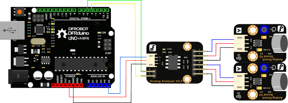 与模拟声音传感器DFR0034连线图
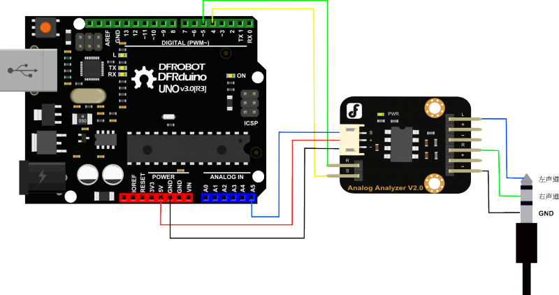 与3.5mm接口声音采集设备连线图
样例代码
- Arduino IDE 样例代码
#include <AudioAnalyzer.h>
//Version 1.3 for Spectrum analyzer
//请下载最新的库文件

Analyzer Audio = Analyzer(4,5,5);//Strobe pin ->4  RST pin ->5 Analog Pin ->5
//Analyzer Audio = Analyzer();//Strobe->4 RST->5 Analog->0

int FreqVal[7];//

void setup()
{
  Serial.begin(57600);
  Audio.Init();//Init module
}

void loop()
{
  Audio.ReadFreq(FreqVal);//返回7个带通滤波器过滤出的的7个对应值
                          //频率(Hz):63  160  400  1K  2.5K  6.25K  16K
                          //FreqVal[]:      0    1    2    3    4    5    6
  for(int i=0;i<7;i++)
  {
    Serial.print(max((FreqVal[i]-100),0));
    if(i<6)  Serial.print(",");
    else Serial.println();
  }
  delay(20);
}- CVAVR 样例代码: 使用 atmega128 (clock 16Mhz), usart0 (波特率:9600), timer1 (scale clock 1024), adc. formula timer1 when use clock freq 16Mhz
Ttimer1 = Periode Timer1 TCNT1 = Register Timer1 N = Scale clock (1, 8, 64, 256 dan 1024) Tosc = Periode clock Fosc = Frekuensi clock cristal
Tosc = 1/Fosc Tosc = 1/16Mhz = 0,0000000625
Ttimer1 = Tosc * (65536 - TCNT1) * N 1 (second) = 0,0000000625 * (65536 - TCNT1) * 1024 TCNT1 = 49911 TCNT1 = C2F7 (in hex) <-- 用于Timer 1溢出中断
Clock value = Fosc/N Clock value = 16Mhz/1024 = 15,625 kHz <-- timer1 时钟频率
可以在程序中使用任一timer
/*****************************************************
Chip type           : ATmega128
Program type        : Application
Clock frequency     : 16,000000 MHz
Memory model        : Small
External SRAM size  : 0
Data Stack size     : 1024
*****************************************************/

int sec, band, freq[7], i;
unsigned long int time_a, time_b;
int stat = 0;

#include <mega128.h>
#include <stdio.h>
#include <delay.h>

// Timer 1 overflow interrupt service routine
interrupt [TIM1_OVF] void timer1_ovf_isr(void)
{
// Reinitialize Timer 1 value
TCNT1H=0xC2F7 >> 8;
TCNT1L=0xC2F7 & 0xff;
// Place your code here
sec++;

}

#define ADC_VREF_TYPE 0x40

// Read the AD conversion result
unsigned int read_adc(unsigned char adc_input)
{

ADMUX=adc_input | (ADC_VREF_TYPE & 0xff);
// Delay needed for the stabilization of the ADC input voltage
delay_us(10);
// Start the AD conversion
ADCSRA|=0x40;
// Wait for the AD conversion to complete
while ((ADCSRA & 0x10)==0);
ADCSRA|=0x10;
return ADCW;

}

void RstModule()
{

PORTD.0 = 0; //S Low
PORTD.1 = 1; //R High
PORTD.0 = 1; //S High
PORTD.0 = 0; //S Low
PORTD.1 = 0; //R Low
delay_us(72);

}

void Init()
{

DDRD.0 = 1; //S pin
DDRD.1 = 1; //R pin
RstModule();

}

void ReadFreq(int *value)
{

if (stat == 0) {
   time_a = sec;
   stat = 1;
} else if (stat == 1) {
   time_b = sec;
   if (time_b - time_a > 3) {
      RstModule();
      stat = 0;
   }
}
for (band=0;band<7;band++) {
   delay_us(10);
   value[band] = read_adc(0);
   delay_us(50);
   PORTD.0 = 1; //S High
   delay_us(18);
   PORTD.0 = 0; //S Low
}

}

void main(void)
{

// Timer/Counter 1 initialization
// Clock source: System Clock
// Clock value: 15,625 kHz
// Mode: Normal top=FFFFh
// OC1A output: Discon.
// OC1B output: Discon.
// OC1C output: Discon.
// Noise Canceler: Off
// Input Capture on Falling Edge
// Timer 1 Overflow Interrupt: On
// Input Capture Interrupt: Off
// Compare A Match Interrupt: Off
// Compare B Match Interrupt: Off
// Compare C Match Interrupt: Off
TCCR1A=0x00;
TCCR1B=0x05;
TCNT1H=0xC2;
TCNT1L=0xF7;
ICR1H=0x00;
ICR1L=0x00;
OCR1AH=0x00;
OCR1AL=0x00;
OCR1BH=0x00;
OCR1BL=0x00;
OCR1CH=0x00;
OCR1CL=0x00;

// Timer(s)/Counter(s) Interrupt(s) initialization
TIMSK=0x04;
ETIMSK=0x00;

// USART0 initialization
// Communication Parameters: 8 Data, 1 Stop, No Parity
// USART0 Receiver: Off
// USART0 Transmitter: On
// USART0 Mode: Asynchronous
// USART0 Baud Rate: 9600
UCSR0A=0x00;
UCSR0B=0x08;
UCSR0C=0x06;
UBRR0H=0x00;
UBRR0L=0x67;

// Analog Comparator initialization
// Analog Comparator: Off
// Analog Comparator Input Capture by Timer/Counter 1: Off
ACSR=0x80;
SFIOR=0x00;

// ADC initialization
// ADC Clock frequency: 1000,000 kHz
// ADC Voltage Reference: AREF pin
ADMUX=ADC_VREF_TYPE & 0xff;
ADCSRA=0x84;

// Global enable interrupts
#asm("sei")

Init();

while (1)
      {
        ReadFreq(freq);

        for (i=0;i<7;i++) {
           printf("%d",freq[i]-100);
           if(i<6) printf(", ");
           else printf("\r\n");
        }

        delay_ms(20);

      };
}
鸣谢: 该代码由论坛友人 Pandora 提供.
相关资料
纠错,疑问,交流: 请进入讨论区或 请点击进入页面,扫码加入微信群或Q群进行交流
获取最新文章: 扫一扫加入“创客智造”公众号