


Pixhawk代码分析-启动代码及入口函数
纠错,疑问,交流: 请进入讨论区或 请点击进入页面,扫码加入微信群或Q群进行交流
获取最新文章: 扫一扫加入“创客智造”公众号
启动代码及入口函数
基础知识
-
- 关于坐标系
1)GeographicCoordinate System
Represents position on earth with alongitude and latitude value (Geographic_coordinate_system). Additionally thealtitude may may be included. The altitude can be expressed as distance fromthe earth center or as altitude above the mean sea level. All in all, thisgives a spherical coordinate system.

2)Earth-Fixed frame
Cartesian coordinate system at the center of the earth. Thepositive z axis goes through the north pole. The x and y axes are on theequatorial plane.3)Body Fixed Frame
The x axis points in forward (defined bygeometry and not by movement) direction. (= roll axis)
The y axis points to the right(geometrically) (= pitch axis)
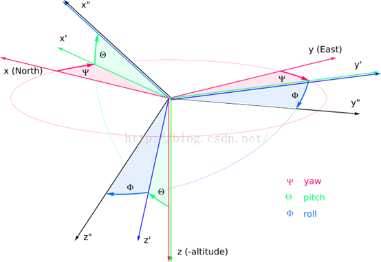
The z axis points downwards (geometrically)(= yaw axis)4)EulerAngles
Usually a conversion between a earth fixed“ground” frame and the body fixed “in-air” frame is described via Euler-Angles.There are multiple conventions of the Euler angles.

    The rotation order for the Tait-Bryan angles is Z Y’X” (see thefigure):
rotation of around Z (yaw) rotation of around Y' (pitch) rotation of around X” (roll)
-
- pixhawk的HAL

- pixhawk的HAL
-
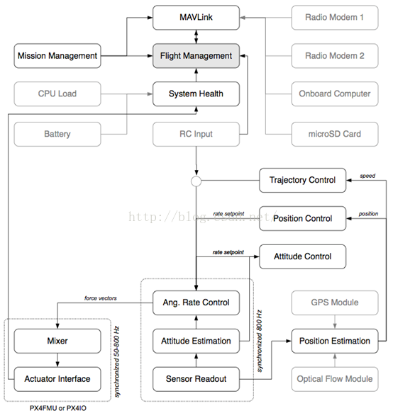
3.pixhawk的控制图
代码分析
1、关于两个控制器和任务优先级
在PX4Firmware/src/modules中的mc_att_control:姿态控制器和mc_pos_control位置控制器(mc:multicopter),整个系统都是围绕着这两个控制器。

    mc_att_control – Multirotor attitude controller

    mc_pos_control – Multirotor position controller

The PX4 firmware is organized in priority bands:-
(interrupt level) fast sensordrivers
-
watchdog/system state monitors
-
actuator outputs (PWM outputdriver thread, IO comms sender thread)
-
attitude controller(s)
-
slow/blocking sensor drivers(must not block attitude controllers)
-
destination/positioncontroller(s)
-
default priority - generic usercode, shell commands, random crap, all RR scheduled
-
logger, parameter syncer
-
idle
2、 关于.mk文件(必须深入理解)
了解整个代码运行过程的最简便方法就是通过其makefile了解文件的包含关系和调用关系。请仔细阅读arducopter中的.mk和modules/PX4Firmware中的.mk文件。.mk文件就是在Linux下编写的一些脚本文件(makefile),类似于编译过程中的条件编译,便于直接使用命令行进行编译链接。
    1)首先介绍上层应用的.mk。在ardupilot/mk/PX4/Tool中px4_common.mk文件中是关于所有PX4平台的通用编译文件,config_px4fmu_v2_APM.mk中针对pixhawk的特有硬件的编译文件。下面实例代码是config_px4fmu_v2_APM.mk中的代码,.mk脚本主要目的是为了选择需要编译的MODULES。


# Makefile for the px4fmu-v2_APM configuration
include $(SKETCHBOOK)/mk/PX4/px4_common.mk
MODULES += drivers/lsm303d
MODULES += drivers/l3gd20
MODULES += drivers/mpu9250
MODULES += drivers/boards/px4fmu-v2
MODULES += drivers/pwm_input
MODULES += modules/uavcan
MODULES += lib/mathlib
MODULES += drivers/px4io
MODULES += drivers/px4flow
MODULES += drivers/oreoled
Makefile的文件夹,指定编译的规则,编译顺序:
ardupilot/ArduCopter/Makefile àmk/apm.mkà environ.mk, targets.mk, sketch_sources.mk, board_px4.mkà find_tools.mk,px4_targets.mk。
尤其是上面的这个px4_targets.mk文件,该文件中涉及了所有的需要编译的文件,最后使用命令行px4-v2编译整个工程,它是最终的编译过程的执行者,注意其中px4-v2规则的详细执行情况,它会去调用PX4Firmware的makefile。下面针对pixhawk硬件平台摘录比较重要一部分。
/*指定PX4Firmware、PX4NuttX、uavcan */
# these can be overridden in developer.mk
PX4FIRMWARE_DIRECTORY ?= $(SKETCHBOOK)/modules/PX4Firmware
PX4NUTTX_DIRECTORY ?= $(SKETCHBOOK)/modules/PX4NuttX
UAVCAN_DIRECTORY ?= $(SKETCHBOOK)/modules/uavcan
PX4_ROOT := $(shell cd $(PX4FIRMWARE_DIRECTORY) && pwd)
NUTTX_ROOT := $(shell cd $(PX4NUTTX_DIRECTORY) && pwd)
NUTTX_SRC := $(NUTTX_ROOT)/nuttx/
UAVCAN_DIR=$(shell cd $(UAVCAN_DIRECTORY) && pwd)/
………
/*选择硬件平台*/
# we have different config files for V1 and V2
PX4_V1_CONFIG_FILE=$(MK_DIR)/PX4/config_px4fmu-v1_APM.mk
PX4_V2_CONFIG_FILE=$(MK_DIR)/PX4/config_px4fmu-v2_APM.mk
PX4_V4_CONFIG_FILE=$(MK_DIR)/PX4/config_px4fmu-v4_APM.mk
………
/*针对pixhawk,请详细了解该部分的实现*/
px4-v2: $(BUILDROOT)/make.flags CHECK_MODULES $(MAVLINK_HEADERS) $(PX4_ROOT)/Archives/px4fmu-v2.export $(SKETCHCPP) module_mk px4-io-v2
    $(RULEHDR)/* PX4_ROOT  = ardupilot/modules/PX4Firmware*/
    $(v) rm -f $(PX4_ROOT)/makefiles/$(PX4_V2_CONFIG_FILE)
    $(v) cp $(PX4_V2_CONFIG_FILE) $(PX4_ROOT)/makefiles/nuttx/
    $(PX4_MAKE) px4fmu-v2_APM
    $(v) /bin/rm -f $(SKETCH)-v2.px4
    $(v) arm-none-eabi-size $(PX4_ROOT)/Build/px4fmu-v2_APM.build/firmware.elf
    $(v) cp $(PX4_ROOT)/Images/px4fmu-v2_APM.px4 $(SKETCH)-v2.px4
    $(v) $(SKETCHBOOK)/Tools/scripts/add_git_hashes.py $(HASHADDER_FLAGS) "$(SKETCH)-v2.px4" "$(SKETCH)-v2.px4"
    $(v) echo "PX4 $(SKETCH) Firmware is in $(SKETCH)-v2.px4"
/*最后编译生成的*.px4文件,直接下载到飞控板中即可实现飞行控制*/
………
px4-clean: clean CHECK_MODULES px4-archives-clean px4-cleandep
    $(v) /bin/rm -rf $(PX4_ROOT)/makefiles/build $(PX4_ROOT)/Build $(PX4_ROOT)/Images/*.px4 $(PX4_ROOT)/Images/*.bin
    $(v) /bin/rm -rf $(PX4_ROOT)/src/modules/uORB/topics $(PX4_ROOT)/src/platforms/nuttx/px4_messages
px4-cleandep: clean
    $(v) find $(PX4_ROOT)/Build -type f -name '*.d' | xargs rm -f
    $(v) find $(UAVCAN_DIRECTORY) -type f -name '*.d' | xargs rm -f
    $(v) find $(SKETCHBOOK)/$(SKETCH) -type f -name '*.d' | xargs rm -f
px4-v2-upload-solo: px4-v2
    scp $(SKETCH)-v2.px4 root@10.1.1.10:/tmp/
    ssh root@10.1.1.10 PYTHONUNBUFFERED=1 loadPixhawk.py /tmp/ArduCopter-v2.px4
    ssh root@10.1.1.10 rm /tmp/ArduCopter-v2.px4;
………
px4-v2-upload: px4-v2
    $(RULEHDR)
    $(v) $(PX4_MAKE) px4fmu-v2_APM upload
px4-upload: px4-v1-upload
px4-archives-clean:
    $(v) /bin/rm -rf $(PX4_ROOT)/Archives


2)接下来就是PX4Firmware中的.mk。如果仔细了解了上面所讲述的,那么这部分就很easy了,不再细讲,自己去看代码吧。需要说明的是在PX4Firmware的makefile文件中有一个README.txt文本,该文本详细的介绍了PX4Firmware中的.mk的调用关系和作用。补充一点,PX4Firmware/makefile/nuttx中的config_px4fmu-v2_default.mk包含了所有基本的模块,从这里再一次验证了开篇讲述的ardupilot的代码是基于pixhawk原生代码PX4Firmware“阉割”而来的。所以在后期做开发的过程中编写应用程序只是按照ardupilot现有的子模块添加自己的就可以,参考mc_att_control实现。
在PX4Firmware/src/modules中添加一个新的文件夹,命名为summer 在summer文件夹中创建module.mk文件,并输入以下内容:
MODULE_COMMAND = summer
SRCS = summer.cpp
在summer文件夹中创建summer.c文件,编译需要实现的功能代码。 注册新添加的应用到NuttShell中:PX4Firmware/makefiles/nuttx/config_px4fmu-v2_default.mk文件中添加如下内容:
MODULES += modules/summer任务的启动就是靠NuttShell的内建命令启动的,包含rcS,特别是rcS一定要了解,下面会详细介绍。
3、关于编译链接库(上层应用库 libraries)
在ardupilot/Arducopter中有一个make.inc文件,指定了编译ArduCopter时需要编译哪些依赖库,它对系统及硬件进行了抽象,以获取更好的可移植性。
http://dev.ardupilot.com/wiki/apmcopter-programming-libraries/
如果想添加或者删除编译的文件,就在此处进行修改。如下是官方默认的。
LIBRARIES += AP_Common
LIBRARIES += AP_Menu
LIBRARIES += AP_Param
LIBRARIES += StorageManager
LIBRARIES += GCS
LIBRARIES += GCS_MAVLink
LIBRARIES += AP_SerialManager
LIBRARIES += AP_GPS
LIBRARIES += DataFlash
LIBRARIES += AP_ADC
LIBRARIES += AP_Baro
LIBRARIES += AP_Compass
LIBRARIES += AP_Math
LIBRARIES += AP_InertialSensor
LIBRARIES += AP_AccelCal
LIBRARIES += AP_AHRS
LIBRARIES += AP_NavEKF
4、启动脚本(rcS:有两个,比较重要,任务分工)
所谓启动脚本其实是用shellscript写的启动文件以前写过比较简单的脚本文件,还是参考的鸟哥的那本书,还有就是Linux启动文件也是用的这个写的,有兴趣的可以去Linux平台下查看一下,会写C的学这个很快,该死的C++什么时候能学会啊。
- 1)其中之一就是负责较为底层driver里面的(比如mpu9250的register map、驱动),在使用命令px4-v2-upload以后,会在modules/PX4Firmware目录下生成build文件夹,内部是编译生成的文件(不编译没有),在modules/PX4Firmware/build/px4fmu-v2_APM.build/romfs_scratch/init.d文件下就是rcS和rc.APM,这个rcS是自启动脚本(setMODE autostart)。rcS脚本会挂载SD卡(这就是没有SD飞控板不能使用的原因所在),然后跳转rc.APM中,该脚本会在pixhawk系统中创建binfs,判断硬件类型,然后启动orb(对,就是那个uORB),然后启动各种传感器,然后咔咔咔,咔咔咔,完了,自己去看脚本吧。摘一部分鉴赏,关于shell脚本的编写自己百度吧,跟C语言的风格很像。
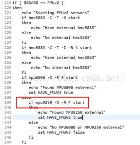
其中类似于mpu9250 start就启动了mpu9250模块的驱动,理解该部分需要结合modules/PX4Firmware/src/drivers/mpu9250中的CMakeLists.txt和module.mk这两个,其中CMakeLists.txt是使用Cmake写的,和module.mk类似,在最新的pixhawk原生代码中删除了make,使用清一色的Cmake。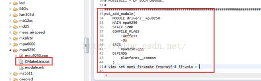
上面标红的MODULE_COMMAND = mpu9250就是为了以后可以直接在.mk文件直接使用的命令mpu9250。理解了上述以后,其他的driver中的所有的传感器模块、各种总线和modules/PX4Firmware/src/modules中的各种算法(mc_att_control、land_detector等等)都是按照此类方法实现的,不在赘述,但是这个rcS只是负责启动driver中的,modules/PX4Firmware/src/modules需要靠下面的一个rcS启动,两个rcS各自分工。全部都是.mk啊,.mk,.mk~~~~
下一阶段主要应该就是放在这个modules/PX4Firmware/src/modules内部了,整个控制响应过程全靠它了,尤其是commander,校磁什么的都在里面,各种calibration,见过2000+行的函数么?!怕么? ~~~ 168MHZ的主频呢,怕啥
PS:需要注意的是,在modules/PX4Firmware/src/drivers/boards/px4fmu-v2中有几个.c文件,其中px4fmu_spi.c和board_config.h。
px4fmu_spi.c 会在入口函数__start()中被调用初始化SPI,下面会提到。
* Name: stm32_spiinitialize
 * Description:
 *   Called to configure SPI chip select GPIO pins for the PX4FMU board.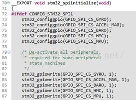
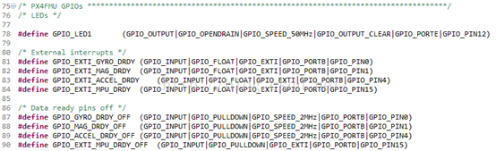
board_config.h:如下的代码是不是很熟悉,用过单片机的肯定都见过,尤其是pixhawk使用的又是STM32,再加上ST公司的芯片在各个高校中的普及程度,虽然我没用过,我是菜鸟。
- 2)另外一个rcS就是modules/PX4Firmware/ROMFS/px4fmu_common/init.d中的rcS,PX4FMU的自启动文件,它主要是负责启动modules/PX4Firmware/modules里面的关于各自控制算法的模块。同时,该rcS会以脚本的形式启动同一级目录中的rc.mc_apps、rc_io等等。详细实现过程参见源代码。
地址:https://github.com/PX4/Firmware/tree/master/ROMFS/px4fmu_common/init.d
举一例说明问题,rc.mc_apps:关于姿态估计、位置估计和姿态控制和位置控制的,源代码如下。
#!nsh
# Standard apps for multirotors:
# att & pos estimator, att & pos control.
# The system is defaulting to INAV_ENABLED = 1
# but users can alternatively try the EKF-based
# filter by setting INAV_ENABLED = 0
if param compare INAV_ENABLED 1
then
    attitude_estimator_q start  //姿态估计
    position_estimator_inav start//位置估计
else
    if param compare LPE_ENABLED 1
    then
        attitude_estimator_q start
        local_position_estimator start
    else
        ekf2 start
    fi
fi
if mc_att_control start //姿态控制
then
else
    # try the multiplatform version
    mc_att_control_m start
fi
if mc_pos_control start //位置控制
then
else
    # try the multiplatform version
    mc_pos_control_m start
fi
# Start Land Detector
land_detector start multicopter //启动落地检测
应该能了解代码中的xxxxx start的含义了吧~~~~还不了解的话请拨打114,有专人为您解答 六、再深入一点
1、主控STM32F4的选择(肯定很多人不知道这个)
在ardupilot/modules/PX4NuttX/nuttx/arch/arm/src/stm32中,主要是通过在stm32_start.c中包含头文件<arch/board/board.h>,board.h中包含<stm32.h>并且配置了STM32的时钟(Clock),stm32.h中包含<chip.h>。另外,stm32.h中还包含了关于stm32的各种Peripherals的头文件,即各种外设(spi、can、uart、i2c等等)的驱动。
在ardupilot/modules/PX4NuttX/nuttx/arch/arm/src/stm32文件下有头文件chip.h,内部通过条件编译执行进行主控MCU的选择。实例代码如下。
/* STM32 F2 Family ******************************************************************/
#elif defined(CONFIG_STM32_STM32F20XX)
#  include "chip/stm32f20xxx_pinmap.h"
/* STM32 F3 Family ******************************************************************/
#elif defined(CONFIG_STM32_STM32F30XX)
#  include "chip/stm32f30xxx_pinmap.h"
/* STM32 F4 Family ******************************************************************/
#elif defined(CONFIG_STM32_STM32F40XX)
#  include "chip/stm32f40xxx_pinmap.h"
#else
#  error "No pinmap file for this STM32 chip"
#endif
2、入口函数(__start())(这个就更不知道了吧)
在ardupilot/modules/PX4NuttX/nuttx/arch/arm/src/stm32文件下有定义文件stm32_start.c,内部有个上电/重启的函数入口__start(void)。仔细看,一行行的看,别偷懒,代码附加列出了几个小问题,检查自己一下都会么?!!!

/****************************************************************************
 * Public Functions
 ****************************************************************************/
/****************************************************************************
 * Name: _start
 *
 * Description:
 *   This is the reset entry point.
 *
 ****************************************************************************/
void __start(void)
{
  const uint32_t *src;
  uint32_t *dest;
#ifdef CONFIG_ARMV7M_STACKCHECK
  /* Set the stack limit before we attempt to call any functions */
  __asm__ volatile ("sub r10, sp, %0" : : "r" (CONFIG_IDLETHREAD_STACKSIZE - 64) : ); /*限制栈大小,可以防止递归把栈内存浪费完了,知道原因么?!*/
#endif
  /* Configure the uart so that we can get debug output as soon as possible */
  stm32_clockconfig();
  stm32_fpuconfig();
  stm32_lowsetup();
  stm32_gpioinit();
  showprogress('A');
  /* Clear .bss.  We'll do this inline (vs. calling memset) just to be
   * certain that there are no issues with the state of global variables.
    inline的好处。
*/
  for (dest = &_sbss; dest < &_ebss; )
    {
      *dest++ = 0;
    }
  showprogress('B');
  /* Move the intialized data section from his temporary holding spot in
   * FLASH into the correct place in SRAM.  The correct place in SRAM is
   * give by _sdata and _edata.  The temporary location is in FLASH at the
   * end of all of the other read-only data (.text, .rodata) at _eronly.
   * 知道上述所讲的几个segments的分布么?!*/
  for (src = &_eronly, dest = &_sdata; dest < &_edata; )
    {
      *dest++ = *src++;
    }
  showprogress('C');
  /* Perform early serial initialization */
#ifdef USE_EARLYSERIALINIT
  up_earlyserialinit();
#endif
  showprogress('D');
  /* For the case of the separate user-/kernel-space(知道几比几么?) build, perform whatever
   * platform specific initialization of the user memory is required.
   * Normally this just means initializing the user space .data and .bss
   * segments.
   */
#ifdef CONFIG_NUTTX_KERNEL
  stm32_userspace();
  showprogress('E');
#endif
  /* Initialize onboard resources */
  stm32_boardinitialize();//初始化SPI(飞控板上的传感器都是通过SPI通信)和LEDs。
                         // 还记上面提到的px4fmu_spi.c么?!
  showprogress('F');
  /* Then start NuttX */
  showprogress('\r');
  showprogress('\n');
  os_start();//还记得上一篇博文的这个么?
  /* Shoulnd't get here */
  for(;;);
}
轻松一下:飞控板上为什么使用SPI而不用I2C?如下是官方原版解释,说白了就是速度问题,如下权当练练English~~~
I2C was not intended by Philips as a high rate sensor bus - this is what SPI has been invented for. Running multiple sensors at a suitably high rateover I2C is not recommended. Our hardware is designed to rely on SPI for allcritical sensors, and is available globally. Given the individual cost of thediscovery kit and sensor boards and power supply, one of the available Pixhawkkits is actually not more expensive, and will save a lot of trouble duringdevelopment and operation.3、 Init sensors
上面那么多传感器必须得初始化以后才能使用啊,所以需要先初始化用到的所有的传感器,在哪配置呢,你找到没?! 在ardupilot/modules/PX4Firmware/src/modules/sensors文件中有定义文件sensor.c(关于飞控板中的各个sensor的初始化函数,以task的方式启动,初始化完成以后kill掉这个task,都是POSIX接口的API)。
首先是sensors_main函数
int sensors_main(int argc, char *argv[])
{
 ………
if (OK != sensors::g_sensors->start()) {  //2293 line number
delete sensors::g_sensors;
sensors::g_sensors = nullptr;
warnx("start failed");
return 1;
}
………
然后捏:start()函数
Int Sensors::start()
{
ASSERT(_sensors_task == -1);
/* start the task */
/*创建任务进程对sensors进行初始化以后,在task_main()函数执行的最后会调用px4_task_exit()函数退出该任务进程*//* px4_task_spawn_cmd()创建任务的接口函数是posix接口的,具体实现参见源码*/
_sensors_task = px4_task_spawn_cmd("sensors", SCHED_DEFAULT,
 SCHED_PRIORITY_MAX - 5,
   2000,
   (px4_main_t)&Sensors::task_main_trampoline,
   nullptr);
/* wait until the task is up and running or has failed */
while (_sensors_task > 0 && _task_should_exit) {
usleep(100);
}
if (_sensors_task < 0) {
return -ERROR;
}
return OK;
}
然后捏:task_main_trampoline()函数:
Void Sensors::task_main_trampoline(int argc, char *argv[])
{
sensors::g_sensors->task_main();
}
再然后捏:task_main()函数,大牌终于出场了
Void Sensors::task_main()
{
/* start individual sensors */
int ret = 0;
do { /* create a scope to handle exit with break *//*do_while用的精妙*/
ret = accel_init();/* return 0 */
if (ret) { break; }
ret = gyro_init();
if (ret) { break; }
ret = mag_init();
if (ret) { break; }
ret = baro_init();
if (ret) { break; }
ret = adc_init();
if (ret) { break; }
break;
} while (0);
………//2059
/*
 * do subscriptions  这就是所谓的IPC使用的uORB模型( publish_subscribe)吧 ,我也不懂
 */
unsigned gcount_prev = _gyro_count;
………
_gyro_count = init_sensor_class(ORB_ID(sensor_gyro), &_gyro_sub[0],
&raw.gyro_priority[0], &raw.gyro_errcount[0]);
………
/* get a set of initial values */
accel_poll(raw);//通过uORB模型获取acc值
gyro_poll(raw);
mag_poll(raw);
baro_poll(raw);
diff_pres_poll(raw);
parameter_update_poll(true /* forced */);
rc_parameter_map_poll(true /* forced */);
………
/* check vehicle status for changes to publication state */
vehicle_control_mode_poll();
/* the timestamp of the raw struct is updated by the gyro_poll() method */
/* copy most recent sensor data */
gyro_poll(raw);
accel_poll(raw);
mag_poll(raw);
baro_poll(raw);
………
/* check battery voltage */
adc_poll(raw);
diff_pres_poll(raw);
/* Inform other processes that new data is available to copy */
if (_publishing && raw.timestamp > 0) {
orb_publish(ORB_ID(sensor_combined), _sensor_pub, &raw);
}
/* keep adding sensors as long as we are not armed,
 * when not adding sensors poll for param updates
 */
if (!_armed && hrt_elapsed_time(&_last_config_update) > 500 * 1000) {
_gyro_count = init_sensor_class(ORB_ID(sensor_gyro), &_gyro_sub[0],
&raw.gyro_priority[0], &raw.gyro_errcount[0]);
_mag_count = init_sensor_class(ORB_ID(sensor_mag), &_mag_sub[0],
       &raw.magnetometer_priority[0], &raw.magnetometer_errcount[0]);
_accel_count = init_sensor_class(ORB_ID(sensor_accel), &_accel_sub[0],
 &raw.accelerometer_priority[0], &raw.accelerometer_errcount[0]);
_baro_count = init_sensor_class(ORB_ID(sensor_baro), &_baro_sub[0],
&raw.baro_priority[0], &raw.baro_errcount[0]);
_last_config_update = hrt_absolute_time();
} else {
/* check parameters for updates */
parameter_update_poll();
/* check rc parameter map for updates */
rc_parameter_map_poll();
}
/* Look for new r/c input data */
rc_poll();
perf_end(_loop_perf);
}
warnx("exiting.");
_sensors_task = -1;
px4_task_exit(ret);/* px4_task_exit ()终止任务的接口函数也是posix接口的*/
}

PS:关于IPC使用的 uORB的简单介绍(摘自官网)。

    The micro Object Request Broker (uORB) application is used toshare data structures between threads and applications,Communications between processes / applications (e.g. sendingsensor values from the sensors app to the attitude filter app) is a key part ofthe PX4 software architecture. Processes (often called nodes in this context) exchange messagesover named buses, called topics.In PX4, a topic contains only one message type, e.g. the vehicle_attitude topic transports a message containing the attitude struct (roll, pitch and yaw estimates). Nodes can publish a message on a bus/topic (“send” data)or subscribe toa bus/topic (“receive” data). They are not aware of who they are communicatingwith. There can be multiple publishers and multiple subscribers to a topic.This design pattern prevents locking issues and is very common in robotics. Tomake this efficient, there is always only one message on the bus and no queue iskept.
详细介绍:https://pixhawk.org/dev/shared_object_communication
4、如何获取精确时间(timestamp)
在控制过程中多数环节都是使用经典的PID控制算法,为了获取较为实时的响应最重要的时间变量,这就涉及如何获取高精度的时间问题。
Pixhawk主控使用ST公司的STM32F4系列处理器,其主频达168MHZ,内部有高精度RTC,以RTC为基准获取精确计时。根据分析源码发现,在modules/PX4Firmware/src/drivers中有一个头文件drv_hrt.h(High-resolutiontimer with callouts and timekeeping),内部对其作出了一部分的介绍,微妙(us)级的精确计时,在中断上下文中调用,与其他函数并行执行不会被堵塞。摘抄几个典型函数如下。
/** Get absolute time.*/
__EXPORT extern hrt_abstime hrt_absolute_time(void);
/** Compute the delta between a timestamp taken in the past and now.
* This function is safe to use even if the timestamp is updated by an interrupt during execution. */
__EXPORT extern hrt_abstime hrt_elapsed_time(const volatile hrt_abstime *then);
/** Store the absolute time in an interrupt-safe fashion.
* This function ensures that the timestamp cannot be seen half-written by an interrupt handler.*/
__EXPORT extern hrt_abstime hrt_store_absolute_time(volatile hrt_abstime *now);
/* initialise a hrt_call structure */
__EXPORT extern void    hrt_call_init(struct hrt_call *entry);
/* Initialise the HRT. */
__EXPORT extern void    hrt_init(void);
针对上述hrt_absolute_time(void)函数做阐述,其他的都类似,它的原型在modules/PX4Firmware/unittests中的hrt.cpp。
hrt_abstime hrt_absolute_time()
{
    struct timeval te;
    gettimeofday(&te, NULL); // get current time
    hrt_abstime us = static_cast<uint64_t>(te.tv_sec) * 1e6 + te.tv_usec; // caculate us
    return us;
}
然后捏:直接进入操作系统(NuttX),轮到操作系统上场了,modules/PX4NuttX/nuttx/schedclock_gettimeofday.c,自己跟踪进去看吧,不在赘述。
接下来可能是继续研究ardupilot这套代码,这套的话就是到上层应用了,即关于loop函数和scheduler_task的问题了;或者转变到pixhawk的原生代码上,这套就是直接到控制算法上
纠错,疑问,交流: 请进入讨论区或 请点击进入页面,扫码加入微信群或Q群进行交流
获取最新文章: 扫一扫加入“创客智造”公众号