


Arduino溶液检测传感器-Analog EC Meter 模拟电导率计
纠错,疑问,交流: 请进入讨论区或 请点击进入页面,扫码加入微信群或Q群进行交流
获取最新文章: 扫一扫加入“创客智造”公众号
概述
- 想DIY一个电导率计吗?还在为没有一款价格低廉、使用方便的电导率计而烦恼吗?对电导率计的来龙去脉感到陌生?不过在DFRobot,陌生感很快就会消失。我们最新推出了一款模拟电导率计,具有连线简单、方便实用等特点。按照示意图连线后,再通过程序控制,就可以非常方便的测量溶液的电导率了。
- 电导率是物质传送电流的能力,是电阻率的倒数。在液体中常以电阻的倒数——电导来衡量其导电能力的大小。水的电导是衡量水质的一个很重要的指标,它能反映出水中存在的电解质的程度。根据水溶液中电解质的浓度不同,则溶液导电的程度也不同。在国际单位制中,电导率的单位称为西门子/米(S/m),其它单位有:S/m,mS/cm,μS/cm。换算关系为:1S/m=1000mS/m=1000000μS/m=10mS/cm=10000μS/cm。
技术指标
- 工作电压:+5.00V
- PCB尺寸:45mm×32mm
- 测量范围:1ms/cm--20ms/cm
- 适用温度:5-40℃
- 精度:<±10%F.S.(具体精度取决于你的校准溶液精度)
- PH2.0接口(3脚贴片)
- BNC接口型电导率电极(电导池常数为1)
- 电导电极线缆长度:大约60厘米
- 防水型DS18B20温度传感器
- 电源指示灯
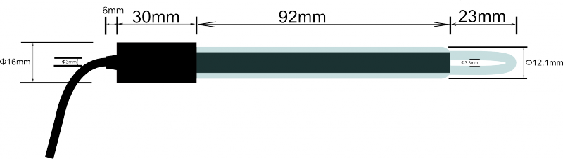
电极尺寸图
电导率计的使用(初级)
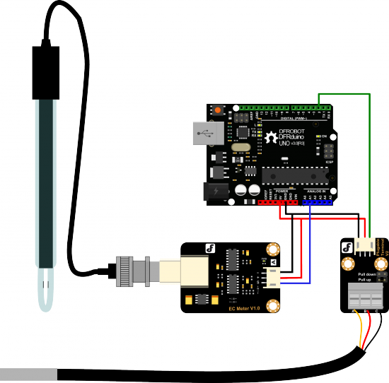
连接图
使用步骤
注意:
- 请使用外接电源,使得EC Meter的供电电压接近+5.00V,电压越准,精度越高。
- 每测量不同的溶液前,需要使用清水清洗电导率电极和温度传感器,以防止示数不准和溶液污染。建议使用去离子水清洗。
- 测量溶液的电导率时,请务必确保温度电极插进被测溶液中,并且用电导电极搅拌溶液,使得电导电极的导电部分充分接触溶液。待温度值和电导率值稳定后,即可读取所需的值。受溶液极化影响,测量高电导率的溶液时,电导率示数会出现一定范围内的抖动。电导率越高,抖动越厉害。
(1)将各个设备按照图示方式连接,即:电导率电极连接到EC Meter电路板的BNC接口,然后用模拟连接线,将EC Meter电路板连接到Arduino主控器的模拟口1。然后把防水型DS18B20温度传感器连接到可插拔传感器转接器的接线端子,然后用数字连接线,连接到Arduino主控器的数字口2。对Arduino主控器供电后,可以看到EC Meter电路板的蓝色指示灯变亮。
(2)对Arduino主控器烧写样例代码。
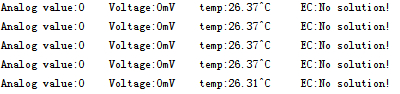
(3)打开Arduino IDE的串口监视器,此时能输出一些参数,如电压值、温度值,并且提示没有溶液。
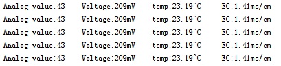
(4)将电导率电极和温度传感器插入校准溶液中,可以测量该溶液的电导率值。搅拌溶液,待示数稳定。如果示数接近标准溶液瓶身所标的值,则可以投入使用。 以测试电导率为1413us/cm的电导率溶液为例:
样例代码
请先下载单总线库。下载样例代码后,打开Arduino IDE的串口监视器,即可看到结果。
#include <OneWire.h>

#define StartConvert 0
#define ReadTemperature 1

const byte numReadings = 20;     //the number of sample times
byte ECsensorPin = A1;  //EC Meter analog output,pin on analog 1
byte DS18B20_Pin = 2; //DS18B20 signal, pin on digital 2
unsigned int AnalogSampleInterval=25,printInterval=700,tempSampleInterval=850;  //analog sample interval;serial print interval;temperature sample interval
unsigned int readings[numReadings];      // the readings from the analog input
byte index = 0;                  // the index of the current reading
unsigned long AnalogValueTotal = 0;                  // the running total
unsigned int AnalogAverage = 0,averageVoltage=0;                // the average
unsigned long AnalogSampleTime,printTime,tempSampleTime;
float temperature,ECcurrent;

//Temperature chip i/o
OneWire ds(DS18B20_Pin);  // on digital pin 2

void setup() {
 // initialize serial communication with computer:
  Serial.begin(115200);
  // initialize all the readings to 0:
  for (byte thisReading = 0; thisReading < numReadings; thisReading++)
    readings[thisReading] = 0;
  TempProcess(StartConvert);   //let the DS18B20 start the convert
  AnalogSampleTime=millis();
  printTime=millis();
  tempSampleTime=millis();
}

void loop() {
  /*
   Every once in a while,sample the analog value and calculate the average.
  */
  if(millis()-AnalogSampleTime>=AnalogSampleInterval)
  {
    AnalogSampleTime=millis();
     // subtract the last reading:
    AnalogValueTotal = AnalogValueTotal - readings[index];
    // read from the sensor:
    readings[index] = analogRead(ECsensorPin);
    // add the reading to the total:
    AnalogValueTotal = AnalogValueTotal + readings[index];
    // advance to the next position in the array:
    index = index + 1;
    // if we're at the end of the array...
    if (index >= numReadings)
    // ...wrap around to the beginning:
    index = 0;
    // calculate the average:
    AnalogAverage = AnalogValueTotal / numReadings;
  }
  /*
   Every once in a while,MCU read the temperature from the DS18B20 and then let the DS18B20 start the convert.
   Attention:The interval between start the convert and read the temperature should be greater than 750 millisecond,or the temperature is not accurate!
  */
   if(millis()-tempSampleTime>=tempSampleInterval)
  {
    tempSampleTime=millis();
    temperature = TempProcess(ReadTemperature);  // read the current temperature from the  DS18B20
    TempProcess(StartConvert);                   //after the reading,start the convert for next reading
  }
   /*
   Every once in a while,print the information on the serial monitor.
  */
  if(millis()-printTime>=printInterval)
  {
    printTime=millis();
    averageVoltage=AnalogAverage*(float)5000/1024;
    Serial.print("Analog value:");
    Serial.print(AnalogAverage);   //analog average,from 0 to 1023
    Serial.print("    Voltage:");
    Serial.print(averageVoltage);  //millivolt average,from 0mv to 4995mV
    Serial.print("mV    ");
    Serial.print("temp:");
    Serial.print(temperature);    //current temperature
    Serial.print("^C     EC:");

    float TempCoefficient=1.0+0.0185*(temperature-25.0);    //temperature compensation formula: fFinalResult(25^C) = fFinalResult(current)/(1.0+0.0185*(fTP-25.0));
    float CoefficientVolatge=(float)averageVoltage/TempCoefficient;
    if(CoefficientVolatge<150)Serial.println("No solution!");   //25^C 1413us/cm<-->about 216mv  if the voltage(compensate)<150,that is <1ms/cm,out of the range
    else if(CoefficientVolatge>3300)Serial.println("Out of the range!");  //>20ms/cm,out of the range
    else
    {
      if(CoefficientVolatge<=448)ECcurrent=6.84*CoefficientVolatge-64.32;   //1ms/cm<EC<=3ms/cm
      else if(CoefficientVolatge<=1457)ECcurrent=6.98*CoefficientVolatge-127;  //3ms/cm<EC<=10ms/cm
      else ECcurrent=5.3*CoefficientVolatge+2278;                           //10ms/cm<EC<20ms/cm
      ECcurrent/=1000;    //convert us/cm to ms/cm
      Serial.print(ECcurrent,2);  //two decimal
      Serial.println("ms/cm");
    }
  }

}
/*
ch=0,let the DS18B20 start the convert;ch=1,MCU read the current temperature from the DS18B20.
*/
float TempProcess(bool ch)
{
  //returns the temperature from one DS18B20 in DEG Celsius
  static byte data[12];
  static byte addr[8];
  static float TemperatureSum;
  if(!ch){
          if ( !ds.search(addr)) {
              Serial.println("no more sensors on chain, reset search!");
              ds.reset_search();
              return 0;
          }
          if ( OneWire::crc8( addr, 7) != addr[7]) {
              Serial.println("CRC is not valid!");
              return 0;
          }
          if ( addr[0] != 0x10 && addr[0] != 0x28) {
              Serial.print("Device is not recognized!");
              return 0;
          }
          ds.reset();
          ds.select(addr);
          ds.write(0x44,1); // start conversion, with parasite power on at the end
  }
  else{
          byte present = ds.reset();
          ds.select(addr);
          ds.write(0xBE); // Read Scratchpad
          for (int i = 0; i < 9; i++) { // we need 9 bytes
            data[i] = ds.read();
          }
          ds.reset_search();
          byte MSB = data[1];
          byte LSB = data[0];
          float tempRead = ((MSB << 8) | LSB); //using two's compliment
          TemperatureSum = tempRead / 16;
    }
          return TemperatureSum;
}
电导率计的使用(高级)
- 采用以上的步骤,你可以轻松测量范围在1ms/cm到20ms/cm之间的溶液电导率值了,但每个电极的电导池常数不一样,因此按照上面的方法获得的结果,精度不会很高。下面将介绍电路的工作原理和校准方案,提高测量精度。这也是仪器分析常用的方法之一。
测量原理
- 请首先打开原理图,找到U3B芯片。
- 这是一个反相比例放大电路,传递函数为:Vo=R10/R*Vi,其中R10是反馈电阻,在图中,其阻值为820欧姆;R是电导电极的电阻,当电导电极插在溶液中,就会出现和溶液电导率相关的电阻值。R10/R称为放大倍数,当R改变时,放大倍数会改变,对输入的电压Vi进行放大输出的Vo会发生变化。
- 反相比例放大电路后面是绝对值电路,传递函数为:Vo=|Vi|。ADOUT就是Arduino模拟采样引脚,因此,测量原理就是电导电极插进不同的溶液中会有不同的电阻值,不同的电阻值会让反相比例放大电路形成不同的放大倍数,然后通过Arduino采样电压值的大小,从而计算出该溶液的电导率值。
下面分析下校准原理。
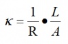
- 电阻定义:

式中,ρ为电阻率;L为电阻体长度;A为电阻体截面。在电导电极中,L表示的是两个导电片之间的间距,A为导电片的面积。
-
电导率的定义:

-
根据上面两个式子,可得:
式中,1/R称为电导G;L/A称为电导池常数Q。- 测量电路的传递函数:
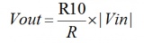
式中,R为电导电极的电阻。- 结合以上的式子,可得:
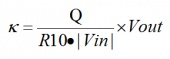
式中,Q为电导池常数,是一个常量,每根电极的电极常数都不同。R10在电路中阻值为820欧姆。|Vin|也是一个常量,取决于信号发生电路,大概200mv左右。因此,电导率和输出电压Vout成线性关系。校准方案
- 根据上述推导的线性关系,可以以电压值Vout为x轴,电导率为y轴,建立坐标系。
- 使用校准液1413us/cm和12.88ms/cm,结合采样得到的电压值,建立直线的解析式。这条直线适合你当前所用的电极,根据这条直线的解析式,就可以得出1ms/cm到20ms/cm之间的电导率值。建议建立这条直线时,使校准液温度维持在25℃。
- 影响电导率的另一个重要因素是温度,因此需要温度补偿,把非25℃的电导率值换算到25℃的值。公式是:Gt = Gtcal{1 + α(T-Tcal)}
其中:Gt为某一温度(°C)下的电导率,Gtcal为标准温度(°C)下的电导率,Tcal为温度修正值,一般为25℃,α为溶液的温度系数,一般取0.0185。- 由于我们按照建立直线的方法,电导率和输出电压成线性关系,因此可以把非25℃的电压值进行补偿,转换到25℃的电压值,再带入直线解析式求电导率值。
- 样例代码是按照这个思路来的,取1.414ms/cm、3ms/cm、10ms/cm、12.88ms/cm建立分段直线解析式,以获得更好的线性关系。
- 电导率电极使用一段时间后,电导池常数会发生变化。因此,可以按照以上方法重新建立新的直线解析式或者使用一点校准法:测得的电导率值除以标准溶液的电导率值得到修正因子,再把这个修正因子乘到原先的直线解析式中即可,相当于改变了直线的斜率。
注意事项
- 电导率电极有光亮和铂黑两种,镀铂黑的目的在于增加电极片的有效面积,减弱电极的极化,测量电导率较大的溶液,使用铂黑电极比较适宜。
- 铂黑电极的铂金片表面附着有疏松的铂黑层,应避免任何物体与其触碰,只能用去离子水进行冲洗,否则会损伤铂黑层,导致电极测量不准确。
- 如发觉铂黑电极使用性能下降,可依次使用无水乙醇和去离子水浸洗铂金片,特别是用户对测量精度要求较高时尤为重要。
- 铂黑电极的铂金片表面附着有疏松的铂黑层,在测量样品时有可能会吸附样品成分,在使用电极测量完毕后一定要及时冲洗电极。
- 电导率电极在放置一段时间或者使用一段时间后,其电极常数有可能发生变化。如用户对测量准确度要求较高,建议按照仪器说明书定期校正电极常数。
相关文档
本文整理于DFRobot wiki
纠错,疑问,交流: 请进入讨论区或 请点击进入页面,扫码加入微信群或Q群进行交流
获取最新文章: 扫一扫加入“创客智造”公众号