


ROS2与Matlab入门教程-使用ROS2和PX4 Bridge控制模拟无人机
纠错,疑问,交流: 请进入讨论区或 请点击进入页面,扫码加入微信群或Q群进行交流
获取最新文章: 扫一扫加入“创客智造”公众号
说明:
- 介绍如何使用 PX4 自动驾驶仪从模拟无人机接收传感器读数和自动驾驶仪状态,并发送控制命令以导航模拟无人机
步骤:
-
设置仿真环境
-
在 MATLAB 中,为px4_msgs包生成自定义消息。您可以将其添加到现有的自定义消息文件夹并重新生成它,或者在此示例文件夹中生成它们。这可能需要一些时间,因为要生成大量消息
unzip("px4_msgs.zip")
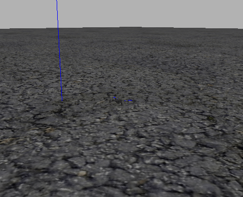
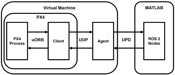
ros2genmsg("custom")- 使用Gazebo 和 Simulated TurtleBot 入门中的说明下载并连接到虚拟机 (VM) 。在 VM 上,通过单击“Gazebo PX4 SITL RTPS”桌面快捷方式启动模拟器和 PX4 Bridge。这会在 Gazebo 中创建一个简单的四旋翼模拟器
- 这也带来了代理microRTPS桥的一半。通信的客户端部分包含在 PX4 Autopilot 包中,并与模拟器一起启动
-
您可以在与 Gazebo 模拟对应的终端上输入 PX4 命令,但本示例不需要这样做
-
设置 ROS 2 网络
-
查看桥代理广播的可用主题。请注意它用来指示发布到 ( out) 和订阅 ( in) 的主题的约定
ros2 topic list

/LaserScan/out
/clock
/fmu/collision_constraints/out
/fmu/debug_array/in
/fmu/debug_key_value/in
/fmu/debug_value/in
/fmu/debug_vect/in
/fmu/offboard_control_mode/in
/fmu/onboard_computer_status/in
/fmu/optical_flow/in
/fmu/position_setpoint/in
/fmu/position_setpoint_triplet/in
/fmu/sensor_combined/out
/fmu/telemetry_status/in
/fmu/timesync/in
/fmu/timesync/out
/fmu/trajectory_bezier/in
/fmu/trajectory_setpoint/in
/fmu/trajectory_waypoint/out
/fmu/vehicle_command/in
/fmu/vehicle_control_mode/out
/fmu/vehicle_local_position_setpoint/in
/fmu/vehicle_mocap_odometry/in
/fmu/vehicle_odometry/out
/fmu/vehicle_status/out
/fmu/vehicle_trajectory_bezier/in
/fmu/vehicle_trajectory_waypoint/in
/fmu/vehicle_trajectory_waypoint_desired/out
/fmu/vehicle_visual_odometry/in
/parameter_events
/rosout
/timesync_status- 创建一个节点来处理无人机的传感器输入和控制反馈。为传感器和感兴趣的信息创建订阅者,并创建发布者以将 UAV 引导至机外控制模式
node = ros2node("/control_node");

% General information about the UAV system
controlModePub = ros2publisher(node,"fmu/offboard_control_mode/in","px4_msgs/OffboardControlMode");
statusSub = ros2subscriber(node,"/fmu/vehicle_status/out","px4_msgs/VehicleStatus");
timeSub = ros2subscriber(node,"fmu/timesync/out","px4_msgs/Timesync");

% Sensor and control communication
odomSub = ros2subscriber(node,"/fmu/vehicle_odometry/out","px4_msgs/VehicleOdometry");
setpointPub = ros2publisher(node,"fmu/trajectory_setpoint/in","px4_msgs/TrajectorySetpoint");
cmdPub = ros2publisher(node,"/fmu/vehicle_command/in","px4_msgs/VehicleCommand");- 从 UAV 状态中获取系统和组件 ID。这些有助于将命令定向到无人机。这还可以确保无人机在进入控制阶段之前启动并运行
timeLimit = 5;
statusMsg = receive(statusSub,timeLimit);
receive(odomSub,timeLimit);
receive(timeSub,timeLimit);-
测试 MATLAB 与 Gazebo 实例的通信
-
使用之前创建的发布者和订阅者指示无人机起飞,飞到新的点,然后着陆。为了执行车外控制,无人机需要控制信息有规律地流动(至少 2 Hz)。在进入车外模式之前启动控制消息是实现此目的的最简单方法
% Start flow of control messages
tStart = tic;
xyz = [0 0 -1]; % NED coordinates - negative Z is higher altitude
while toc(tStart) < 1
    publishOffboardControlMode(timeSub,controlModePub,"position")
    publishTrajectorySetpoint(timeSub,setpointPub,xyz)
    pause(0.1)
end

% Instruct the UAV to accept offboard commands
% Arm the UAV so it allows flying
engageOffboardMode(timeSub,cmdPub)
arm(timeSub,cmdPub)

% Navigate to a nearby location and hover there
while toc(tStart) < 21
    publishOffboardControlMode(timeSub,controlModePub,"position")
    publishTrajectorySetpoint(timeSub,setpointPub,xyz)
    pause(0.1)
end

% Land once complete
land(timeSub,cmdPub)-
从 Simulink 控制无人机
-
您还可以使用 Simulink® 模型控制无人机ControlUAVUsingROS2。Simulink 模型包括四个主要子系统:Arm、Offboard、Takeoff 和 Waypoint 跟随和避障
open_system("ControlUAVUsingROS2.slx");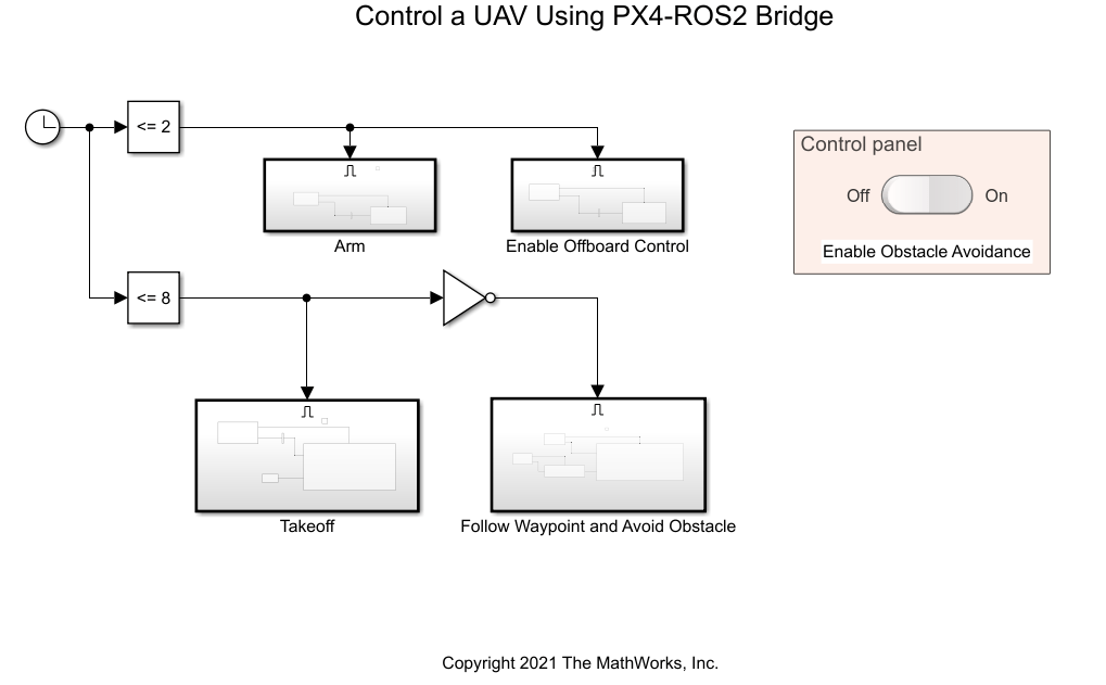
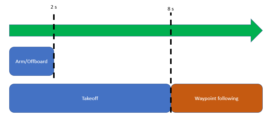
- 时钟模块根据模拟时间触发不同的无人机活动。模型在 PX4 自动驾驶仪的前 2 秒内武装并启用非车载控制模式。它发出起飞命令,在前 8 秒内将无人机带到离地面 1 米的高度,然后它会进行航路点跟踪行为
- 您可以使用控制面板启用或禁用避障行为
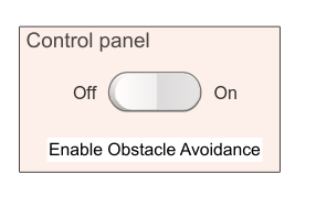
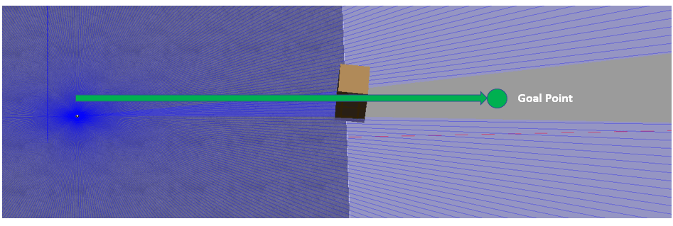
- 如果关闭避障功能,无人机会沿着直线路径飞向障碍物箱后面的目标点,从而导致碰撞。如果启用了避障功能,无人机会根据激光雷达传感器读数尝试飞越障碍物
-
在 VM 中启动新的 PX4-SITL 和 Gazebo 实例后,您可以运行模型并观察无人机的飞行行为
-
辅助函数
function arm(timeSub,cmdPub)
% Allow UAV flight
    cmdMsg = ros2message(cmdPub);
    cmdMsg.command = uint32(cmdMsg.VEHICLE_CMD_COMPONENT_ARM_DISARM);
    cmdMsg.param1 = single(1);
    publishVehicleCommand(timeSub,cmdPub,cmdMsg)
end

function land(timeSub,cmdPub)
% Land the UAV
    cmdMsg = ros2message(cmdPub);
    cmdMsg.command = uint32(cmdMsg.VEHICLE_CMD_NAV_LAND);
    publishVehicleCommand(timeSub,cmdPub,cmdMsg)
end

function engageOffboardMode(timeSub,cmdPub)
% Allow offboard control messages to be utilized
    cmdMsg = ros2message(cmdPub);
    cmdMsg.command = uint32(cmdMsg.VEHICLE_CMD_DO_SET_MODE);
    cmdMsg.param1 = single(1);
    cmdMsg.param2 = single(6);
    publishVehicleCommand(timeSub,cmdPub,cmdMsg)
end

function publishOffboardControlMode(timeSub,controlModePub,controlType)
% Set the type of offboard control to be used
% controlType must match the field name in the OffboardControlMode message
    modeMsg = ros2message(controlModePub);
    modeMsg.timestamp = timeSub.LatestMessage.timestamp;
    % Initially set all to false
    modeMsg.position = false;
    modeMsg.velocity = false;
    modeMsg.acceleration = false;
    modeMsg.attitude = false;
    modeMsg.body_rate = false;
    % Override desired control mode to true
    modeMsg.(controlType) = true;
    send(controlModePub,modeMsg)
end

function publishTrajectorySetpoint(timeSub,setpointPub, xyz)

    setpointMsg = ros2message(setpointPub);
    setpointMsg.timestamp = timeSub.LatestMessage.timestamp;
    setpointMsg.x = single(xyz(1));
    setpointMsg.y = single(xyz(2));
    setpointMsg.z = single(xyz(3));
    send(setpointPub,setpointMsg)
end

function publishVehicleCommand(timeSub,cmdPub,cmdMsg)
    cmdMsg.timestamp = timeSub.LatestMessage.timestamp;
    cmdMsg.target_system = uint8(1);
    cmdMsg.target_component = uint8(1);
    cmdMsg.source_system = uint8(1);
    cmdMsg.source_component = uint8(1);
    cmdMsg.from_external = true;
    send(cmdPub,cmdMsg)
end
纠错,疑问,交流: 请进入讨论区或 请点击进入页面,扫码加入微信群或Q群进行交流
获取最新文章: 扫一扫加入“创客智造”公众号