


Arduino内置教程-通讯-调光器
调光器
这个例子展示怎么从个人电脑发送数据到Arduino或者Genuino开发板来控制LED的亮度。这个数据是用特定的字节发送,每个数据的范围从0-255.程序读取三个字节,并且用它来设置LED的亮度。
你可以从任何可以接入电脑串口的软件发送字节到开发板。例如下面示范的Processing 和 Max/MSP version 5。
硬件要求
- Arduino 或 Genuino 开发板
- LED
- 220 ohm 电阻
软件要求
- Processing 或者 Max/MSP version 5
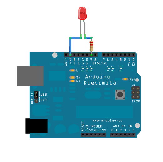
电路
LED灯串联一个220 ohm限流电阻,再连接到数字引脚pin9。LED的长腿(正极或者阳极)应该连到电阻的输出端,而短腿(负极或者阴极)连接到地。
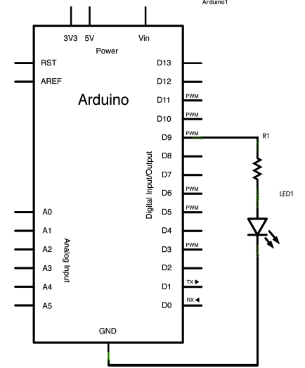
原理图
样例代码
/*
  Dimmer

 Demonstrates the sending data from the computer to the Arduino board,
 in this case to control the brightness of an LED.  The data is sent
 in individual bytes, each of which ranges from 0 to 255.  Arduino
 reads these bytes and uses them to set the brightness of the LED.

 The circuit:
 LED attached from digital pin 9 to ground.
 Serial connection to Processing, Max/MSP, or another serial application

 created 2006
 by David A. Mellis
 modified 30 Aug 2011
 by Tom Igoe and Scott Fitzgerald

 This example code is in the public domain.

 http://www.arduino.cc/en/Tutorial/Dimmer

 */

const int ledPin = 9;      // the pin that the LED is attached to

void setup() {
  // initialize the serial communication:
  Serial.begin(9600);
  // initialize the ledPin as an output:
  pinMode(ledPin, OUTPUT);
}

void loop() {
  byte brightness;

  // check if data has been sent from the computer:
  if (Serial.available()) {
    // read the most recent byte (which will be from 0 to 255):
    brightness = Serial.read();
    // set the brightness of the LED:
    analogWrite(ledPin, brightness);
  }
}

/* Processing code for this example
 // Dimmer - sends bytes over a serial port
 // by David A. Mellis
 //This example code is in the public domain.

 import processing.serial.*;
 Serial port;

 void setup() {
 size(256, 150);

 println("Available serial ports:");
 // if using Processing 2.1 or later, use Serial.printArray()
 println(Serial.list());

 // Uses the first port in this list (number 0).  Change this to
 // select the port corresponding to your Arduino board.  The last
 // parameter (e.g. 9600) is the speed of the communication.  It
 // has to correspond to the value passed to Serial.begin() in your
 // Arduino sketch.
 port = new Serial(this, Serial.list()[0], 9600);

 // If you know the name of the port used by the Arduino board, you
 // can specify it directly like this.
 //port = new Serial(this, "COM1", 9600);
 }

 void draw() {
 // draw a gradient from black to white
 for (int i = 0; i < 256; i++) {
 stroke(i);
 line(i, 0, i, 150);
 }

 // write the current X-position of the mouse to the serial port as
 // a single byte
 port.write(mouseX);
 }
 */

/* Max/MSP v5 patch for this example

----------begin_max5_patcher----------
1008.3ocuXszaiaCD9r8uhA5rqAeHIa0aAMaAVf1S6hdoYQAsDiL6JQZHQ2M
YWr+2KeX4vjnjXKKkKhhiGQ9MeyCNz+X9rnMp63sQvuB+MLa1OlOalSjUvrC
ymEUytKuh05TKJWUWyk5nE9eSyuS6jesvHu4F4MxOuUzB6X57sPKWVzBLXiP
xZtGj6q2vafaaT0.BzJfjj.p8ZPukazsQvpfcpFs8mXR3plh8BoBxURIOWyK
rxspZ0YI.eTCEh5Vqp+wGtFXZMKe6CZc3yWZwTdCmYW.BBkdiby8v0r+ST.W
sD9SdUkn8FYspPbqvnBNFtZWiUyLmleJWo0vuKzeuj2vpJLaWA7YiE7wREui
FpDFDp1KcbAFcP5sJoVxp4NB5Jq40ougIDxJt1wo3GDZHiNocKhiIExx+owv
AdOEAksDs.RRrOoww1Arc.9RvN2J9tamwjkcqknvAE0l+8WnjHqreNet8whK
z6mukIK4d+Xknv3jstvJs8EirMMhxsZIusET25jXbX8xczIl5xPVxhPcTGFu
xNDu9rXtUCg37g9Q8Yc+EuofIYmg8QdkPCrOnXsaHwYs3rWx9PGsO+pqueG2
uNQBqWFh1X7qQG+3.VHcHrfO1nyR2TlqpTM9MDsLKNCQVz6KO.+Sfc5j1Ykj
jzkn2jwNDRP7LVb3d9LtoWBAOnvB92Le6yRmZ4UF7YpQhiFi7A5Ka8zXhKdA
4r9TRGG7V4COiSbAJKdXrWNhhF0hNUh7uBa4Mba0l7JUK+omjDMwkSn95Izr
TOwkdp7W.oPRmNRQsiKeu4j3CkfVgt.NYPEYqMGvvJ48vIlPiyzrIuZskWIS
xGJPcmPiWOfLodybH3wjPbMYwlbFIMNHPHFOtLBNaLSa9sGk1TxMzCX5KTa6
WIH2ocxSdngM0QPqFRxyPHFsprrhGc9Gy9xoBjz0NWdR2yW9DUa2F85jG2v9
FgTO4Q8qiC7fzzQNpmNpsY3BrYPVJBMJQ1uVmoItRhw9NrVGO3NMNzYZ+zS7
3WTvTOnUydG5kHMKLqAOjTe7fN2bGSxOZDkMrBrGQ9J1gONBEy0k4gVo8qHc
cxmfxVihWz6a3yqY9NazzUYkua9UnynadOtogW.JfsVGRVNEbWF8I+eHtcwJ
+wLXqZeSdWLo+FQF6731Tva0BISKTx.cLwmgJsUTTvkg1YsnXmxDge.CDR7x
D6YmX6fMznaF7kdczmJXwm.XSOOrdoHhNA7GMiZYLZZR.+4lconMaJP6JOZ8
ftCs1YWHZI3o.sIXezX5ihMSuXzZtk3ai1mXRSczoCS32hAydeyXNEu5SHyS
xqZqbd3ZLdera1iPqYxOm++v7SUSz
-----------end_max5_patcher-----------
 */
Processing代码
上面代码例子的Processing 程序将会通过电脑的串口发送字节到开发板上来使LED熄灭。
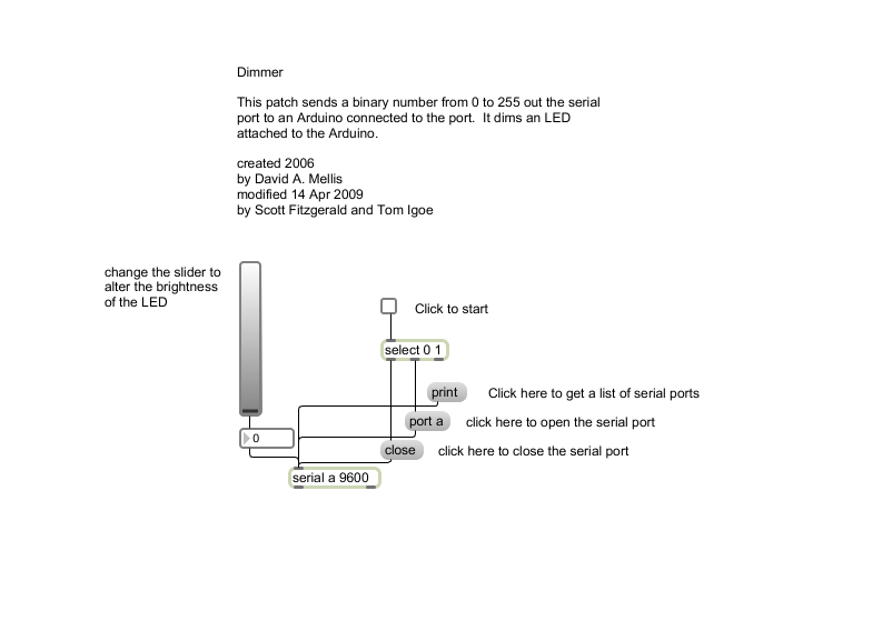
Max 代码
上面代码例子的Max/MSP补丁看起来像是下面的图片。复制它,然后粘贴到一个新的补丁窗口
更多
- serial()
- serial.read()
- analogRead()
- analogWrite()
- ASCIITable - 示范使用Arduino的高等的串口输出函数。
- Graph - 发送数据到电脑,然后在Processing里画出它的图表。
- Midi - 连续发送MIDI音符信息
- MultiSerialMega - 使能Arduino Mega上2个串口。
- PhysicalPixel - 通过从Processing或者Max/MSP发送数据到Arduino上,使LED开关。
- ReadASCIIString - 分析整数里一个用逗号分隔的字符串,来使一个LED灯褪色。
- SerialCallResponse - 通过一个呼-应的方法(握手)来发送多个变数
- SerialCallResponseASCII - 通过一个呼-应的方法(握手)来发送多个变数,并在发送前解码(ASCII)这些数值。
- SerialEvent - 使用SerialEvent()函数
- VirtualColorMixer - 从Arduino发送多个变数到你的电脑,然后在Processing或者Max/MSP上读取这些数据
获取最新文章: 扫一扫右上角的二维码加入“创客智造”公众号