


Arduino内置教程-模拟-校准
纠错,疑问,交流: 请进入讨论区或 请点击进入页面,扫码加入微信群或Q群进行交流
获取最新文章: 扫一扫加入“创客智造”公众号
校准
这个例子展示一种矫正传感输入的技巧。这个开发板在启动时让传感器读取5秒钟,记录最高和最低值的轨迹。这些在程序里执行5秒的传感读取数定义为循环下一次读取的期望值的最小值和最大值。
硬件要求
- Arduino 或者 Genuino开发板
- LED
- 模拟感应器 (光敏电阻可以做到)
- 10k ohm 电阻
- 220 ohm 电阻
- 连接线
- 面包板
电路
模拟传感器(如电位计,光传感器)在模拟输入A2上。LED在数字引脚pin9上。
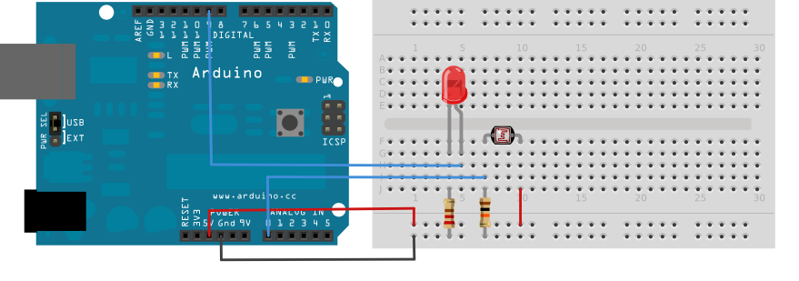
把一个LED灯通过220 ohm限流电阻连接到数字引脚pin9。把一个光敏电阻的一端连接到5V。另一端连接到pin0,并通过10k ohm电阻下拉到地。
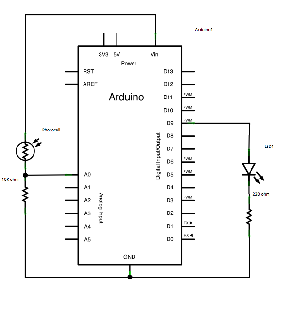
原理图
样例代码
- 在启动函数前,你要为最大值和最小值设置初始值,如:
int sensorMin = 1023;        // minimum sensor value
int sensorMax = 0; // maximum sensor value- 这些可能看起来反了。开始时,你设置最大的高电平,然后读取任何比它低的值,将它作为新的最小值保存。同样地,你设置最小的低电平,然后读取任何比它高的值,将它作为新的最大值保存。就像这样:
// calibrate during the first five seconds
 while (millis() < 5000) {
   sensorValue = analogRead(sensorPin);

   // record the maximum sensor value
   if (sensorValue > sensorMax) {
     sensorMax = sensorValue;
   }

   // record the minimum sensor value
   if (sensorValue < sensorMin) {
     sensorMin = sensorValue;
   }
}- 这种方式下,你做的更多读取可能会根据这个最大值和最小值按比例分配。就像这样:
// apply the calibration to the sensor reading
sensorValue = map(sensorValue, sensorMin, sensorMax, 0, 255);- 这里有全部程序:
/*
  Calibration

 Demonstrates one technique for calibrating sensor input.  The
 sensor readings during the first five seconds of the sketch
 execution define the minimum and maximum of expected values
 attached to the sensor pin.

 The sensor minimum and maximum initial values may seem backwards.
 Initially, you set the minimum high and listen for anything
 lower, saving it as the new minimum. Likewise, you set the
 maximum low and listen for anything higher as the new maximum.

 The circuit:
 * Analog sensor (potentiometer will do) attached to analog input 0
 * LED attached from digital pin 9 to ground

 created 29 Oct 2008
 By David A Mellis
 modified 30 Aug 2011
 By Tom Igoe

 http://www.arduino.cc/en/Tutorial/Calibration

 This example code is in the public domain.

 */

// These constants won't change:
const int sensorPin = A0;    // pin that the sensor is attached to
const int ledPin = 9;        // pin that the LED is attached to

// variables:
int sensorValue = 0;         // the sensor value
int sensorMin = 1023;        // minimum sensor value
int sensorMax = 0;           // maximum sensor value


void setup() {
  // turn on LED to signal the start of the calibration period:
  pinMode(13, OUTPUT);
  digitalWrite(13, HIGH);

  // calibrate during the first five seconds
  while (millis() < 5000) {
    sensorValue = analogRead(sensorPin);

    // record the maximum sensor value
    if (sensorValue > sensorMax) {
      sensorMax = sensorValue;
    }

    // record the minimum sensor value
    if (sensorValue < sensorMin) {
      sensorMin = sensorValue;
    }
  }

  // signal the end of the calibration period
  digitalWrite(13, LOW);
}

void loop() {
  // read the sensor:
  sensorValue = analogRead(sensorPin);

  // apply the calibration to the sensor reading
  sensorValue = map(sensorValue, sensorMin, sensorMax, 0, 255);

  // in case the sensor value is outside the range seen during calibration
  sensorValue = constrain(sensorValue, 0, 255);

  // fade the LED using the calibrated value:
  analogWrite(ledPin, sensorValue);
}更多
- while()
- millis()
- constrain()
- map()
- If
- AnalogInOutSerial - 读取一个模拟输入引脚,按比例划分读数,然后用这个数据来熄灭或者点亮一个LED灯
- AnalogInput - 用电位计来控制LED灯闪烁
- AnalogWriteMega - 用一个Arduino或者Genuino Mega开发板来使12个LED灯一个接一个逐渐打开和熄灭
- Fading - 用模拟输出(PWM引脚)来使LED灯变亮或者变暗
- Smoothing - 使多个模拟输入引脚的读取值变得平滑
纠错,疑问,交流: 请进入讨论区或 请点击进入页面,扫码加入微信群或Q群进行交流
获取最新文章: 扫一扫加入“创客智造”公众号