


Arduino内置教程-模拟-模拟输入
纠错,疑问,交流: 请进入讨论区或 请点击进入页面,扫码加入微信群或Q群进行交流
获取最新文章: 扫一扫加入“创客智造”公众号
模拟输入
在这个例子里我们用一个变化电阻(一个电位计或者光敏电阻),我们通过Arduino或者Genuino开发板的一个模拟输入引脚读取它的值,并且根据这个值改变内置LED灯闪烁的速率。这个电阻的模拟值是作为电压读取,因为这是模拟输入的工作方式。
硬件要求
- Arduino or Genuino 开发板
- 电位计 或者 10K ohm 光敏电阻和 10K ohm 电阻
- pin13引脚的内置LED灯 或者 220 ohm 电阻和红色LED灯
电路
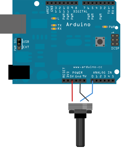
带电位计:
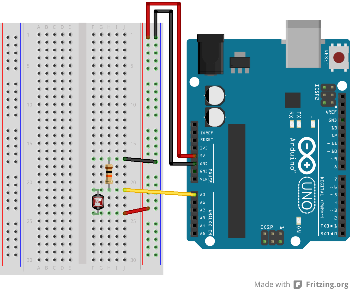
带光敏电阻:
-
连接三根线到开发板。第一根从地到电位计的一个引脚。第二根从5V到电位计的另一个引脚。第三跟从模拟输入引脚A0到电位计的中间引脚。
-
这个例子里,可以使用开发板的连接到pin13的内置LED灯。如果用外加的LED灯,把它的长脚(正极或者阳极)串联一个220 ohm电阻,再连接到数字引脚pin13,而它的短脚(负极或者阴极)连接到pin13旁边的GND引脚(地)
-
这个电路基于光敏电阻,用一个分压器来使高阻抗模拟输入引脚来测量电压值。这些输入引脚不吸取任何电流,因而根据欧姆定律,这些在电阻的一端连接到5V的被测量的电压等于5V,而不管这些电阻值。为了获得按光敏电阻值匹配的电压值,一个电阻分压器是很有必要的。这个电路用一个可变电阻器,一个固定电阻,而测量点是在这些电阻值的中间。测量的电压(VOUT)符合以下公式:
Vout=Vin*(R2/(R1+R2))其中Vin为5V,R2为10kohm和R1为光敏电阻值(范围从在黑暗的1M ohm到在亮处(10lumen)的10k ohm,再到光亮处(>100lumen)的1k ohm)。
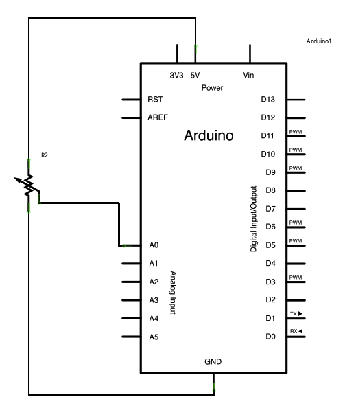
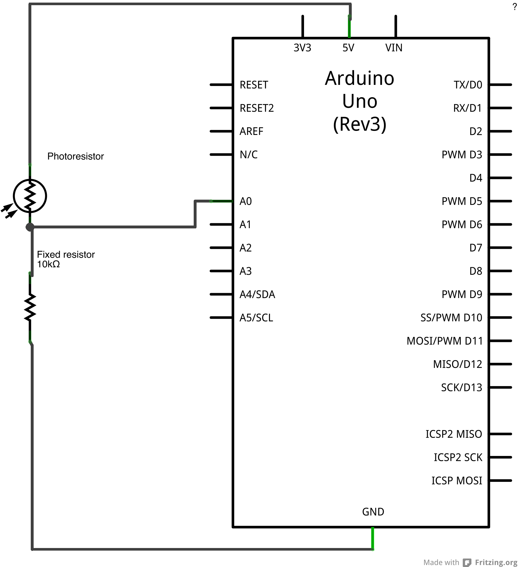
原理图
电位计:
光敏电阻:
样例代码
-
在程序开始部分,变量感应引脚被设置为模拟引脚A0,那个地方连接着电位计。ledPin被设置为数字引脚pin13.你也可以创建另外的变量,sensorValue来保存从你传感器里读到的值。
-
用 analogRead() 命令转化输入电压范围(0-5V)到数字值(0-1023)。这个可以用叫模拟数字转换器或者ADC的微控制器来实现。
-
通过转动电位计的轴,你可以改变电位计的电阻值。这会改变在中间引脚和其他两个外接引脚之间的电阻值,在模拟输入引脚处产生一个电压差。当轴转向一个方向,中间引脚和地引脚没有阻抗。中间引脚的电压值为0V,并且analogRead()返回0.当轴转向另一个方向,中间引脚和5V引脚没有阻抗。中间引脚的电压值为5V,并且analogRead()返回1023。转轴在之间时,analogRead()返回0-1023之间的一个数。
这个值,保存到sensorValue,用来为你的闪烁周期设置 delay() 。这个值越高,周期越长;越低,周期越短。在周期循环之前读取这个值,因此每次开/关的时间总是一样的。
/*
  Analog Input
 Demonstrates analog input by reading an analog sensor on analog pin 0 and
 turning on and off a light emitting diode(LED)  connected to digital pin 13.
 The amount of time the LED will be on and off depends on
 the value obtained by analogRead().

 The circuit:
 * Potentiometer attached to analog input 0
 * center pin of the potentiometer to the analog pin
 * one side pin (either one) to ground
 * the other side pin to +5V
 * LED anode (long leg) attached to digital output 13
 * LED cathode (short leg) attached to ground

 * Note: because most Arduinos have a built-in LED attached
 to pin 13 on the board, the LED is optional.


 Created by David Cuartielles
 modified 30 Aug 2011
 By Tom Igoe

 This example code is in the public domain.

 http://www.arduino.cc/en/Tutorial/AnalogInput

 */

int sensorPin = A0;    // select the input pin for the potentiometer
int ledPin = 13;      // select the pin for the LED
int sensorValue = 0;  // variable to store the value coming from the sensor

void setup() {
  // declare the ledPin as an OUTPUT:
  pinMode(ledPin, OUTPUT);
}

void loop() {
  // read the value from the sensor:
  sensorValue = analogRead(sensorPin);
  // turn the ledPin on
  digitalWrite(ledPin, HIGH);
  // stop the program for <sensorValue> milliseconds:
  delay(sensorValue);
  // turn the ledPin off:
  digitalWrite(ledPin, LOW);
  // stop the program for for <sensorValue> milliseconds:
  delay(sensorValue);
}更多
- pinMode()
- analogRead()
- digitalWrite()
- delay()
- AnalogInOutSerial - 读取一个模拟输入引脚,按比例划分读数,然后用这个数据来熄灭或者点亮一个LED灯
- AnalogWriteMega - 用一个Arduino或者Genuino Mega开发板来使12个LED灯一个接一个逐渐打开和熄灭
- Calibration - 定义期望中的模拟传感值的最大值和最小值
- Fading - 用模拟输出(PWM引脚)来使LED灯变亮或者变暗
- Smoothing - 使多个模拟输入引脚的读取值变得平滑
纠错,疑问,交流: 请进入讨论区或 请点击进入页面,扫码加入微信群或Q群进行交流
获取最新文章: 扫一扫加入“创客智造”公众号