


Arduino内置教程-传感器-ADXL3xx
ADXL3xx 加速计
这个教程示范怎么读取ADXL3xx系列的模拟加速计设备(如ADXL320, ADXL321, ADXL322, ADXL330),并且通过IDE串口监视器或者其他应用传达加速度到个人电脑里。
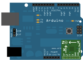
这个教程是用Sparkfun的开源板。adafruit加速计开源板同样可以工作,尽管需要不同的连线。
ADXL3xx的输出(加速计的每个轴)是作为模拟电压输出,范围在0到5V之间。你只需要用analogRead()读取这个值。
硬件要求
- Arduino or Genuino 开发板
- ADXL3xx 加速计
电路
这个加速计用很少电路,所以它能插在你的开发板上直接运行。为了实现这个目的,你要用三个模拟输出引脚作为数字I/O引脚,为加速计提供电源和地,还有自检引脚。你要用其他三个模拟输入引脚来读取加速计的模拟输出。
原理图
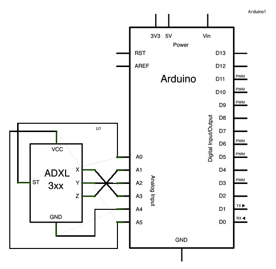
- 这是引脚配置连接表格:
| Breakout Board Pin | Self-Test | Z-Axis | Y-Axis | X-Axis | Ground | VDD |
| Arduino Analog Input Pin | 0 | 1 | 2 | 3 | 4 | 5 |
- 或者如果你只用加速计:
| ADXL3xx Pin | Self-Test | ZOut | YOut | XOut | Ground | VDD |
| Arduino Pin | None (unconnected) | Analog Input 1 | Analog Input 2 | Analog Input 3 | GND | 5V |
- 注意有些加速计用3.3V电源,可能会被5V电源损伤。检查供应商的记录,找出哪种电压合适。
样例代码
- 加速计连接用作提供电源的两个引脚pin4和pin5在程序的开始被定义为常量。而实际操作引脚是作为数字I/O引脚pin18和pin19使用。如果需要,A0是D14,A1是D15等等。
const int groundpin = 18;
const int powerpin = 19;
- 设置pin19(A5)为高电平,pin18(A4)为低电平来提供5V给加速计(加速计工作只需要微量电流)。
pinMode(groundpin, OUTPUT);
pinMode(powerpin, OUTPUT);
digitalWrite(groundpin, LOW);
digitalWrite(powerpin, HIGH);
- 这个方法允许Sparkfun的开源板直接连接到Arduino或者Genuino开发板。不同板可能要连接到标准的5V或者3.3V和地引脚。在接下来的状况,这个代码可能在void setup()部分改进。
/*
 ADXL3xx

 Reads an Analog Devices ADXL3xx accelerometer and communicates the
 acceleration to the computer.  The pins used are designed to be easily
 compatible with the breakout boards from Sparkfun, available from:
 http://www.sparkfun.com/commerce/categories.php?c=80

 http://www.arduino.cc/en/Tutorial/ADXL3xx

 The circuit:
 analog 0: accelerometer self test
 analog 1: z-axis
 analog 2: y-axis
 analog 3: x-axis
 analog 4: ground
 analog 5: vcc

 created 2 Jul 2008
 by David A. Mellis
 modified 30 Aug 2011
 by Tom Igoe

 This example code is in the public domain.

*/

// these constants describe the pins. They won't change:
const int groundpin = 18;             // analog input pin 4 -- ground
const int powerpin = 19;              // analog input pin 5 -- voltage
const int xpin = A3;                  // x-axis of the accelerometer
const int ypin = A2;                  // y-axis
const int zpin = A1;                  // z-axis (only on 3-axis models)

void setup() {
  // initialize the serial communications:
  Serial.begin(9600);

  // Provide ground and power by using the analog inputs as normal
  // digital pins.  This makes it possible to directly connect the
  // breakout board to the Arduino.  If you use the normal 5V and
  // GND pins on the Arduino, you can remove these lines.
  pinMode(groundpin, OUTPUT);
  pinMode(powerpin, OUTPUT);
  digitalWrite(groundpin, LOW);
  digitalWrite(powerpin, HIGH);
}

void loop() {
  // print the sensor values:
  Serial.print(analogRead(xpin));
  // print a tab between values:
  Serial.print("\t");
  Serial.print(analogRead(ypin));
  // print a tab between values:
  Serial.print("\t");
  Serial.print(analogRead(zpin));
  Serial.println();
  // delay before next reading:
  delay(100);
}
数据
- 这里是一些由ADXL322 2g加速计对地角度采集的y轴加速读取值。这些值应该和其他轴的一样,只不过变化取决于设备的精度。在水平轴(即是和地平行或者0°),加速计读取值应该大约是512,但这些在其他角度的值可能伴随不同加速计而不同。(如ADXL302 5g)。
| Angle | -90 | -80 | -70 | -60 | -50 | -40 | -30 | -20 | -10 | 0 |
| Acceleration | 662 | 660 | 654 | 642 | 628 | 610 | 589 | 563 | 537 | 510 |
| Angle | 0 | 10 | 20 | 30 | 40 | 50 | 60 | 70 | 80 | 90 |
| Acceleration | 510 | 485 | 455 | 433 | 408 | 390 | 374 | 363 | 357 | 355 |
更多
- pinMode()
- digitalWrite()
- analogRead()
- serial.begin()
- serial.print()
- 模拟输入 - 用电位计来控制LED灯变亮或者变暗
- 模拟串口输入输出 - 读取一个模拟输入,匹配它的值,然后根据最后的值使LED灯变亮或者变暗。
- ADXL3xx: 读取一个 ADXL3xx 加速计
- Knock: 通过一个压电元件来侦察敲击
- Memsic2125: 2轴加速计
- Ping: 通过一个超声波测距仪来侦察物品
获取最新文章: 扫一扫右上角的二维码加入“创客智造”公众号