


Arduino内置教程-显示-行列扫描
纠错,疑问,交流: 请进入讨论区或 请点击进入页面,扫码加入微信群或Q群进行交流
获取最新文章: 扫一扫加入“创客智造”公众号
行列扫描来控制8x8 LED矩阵
-
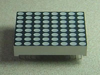
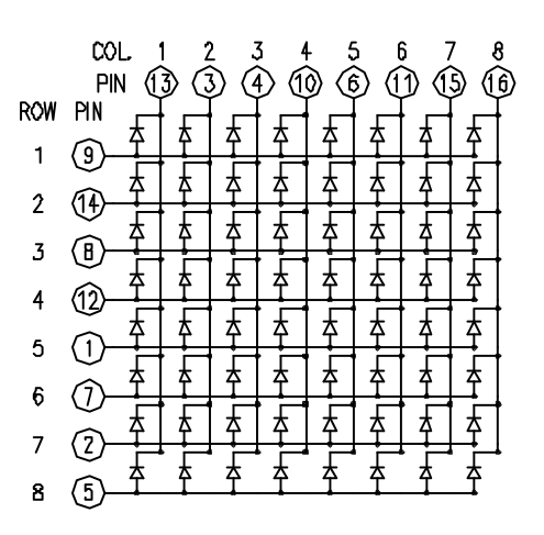
LED灯显示经常打包成一个8x8 LED矩阵,行是共阳极,列是共阴极,或者反过来。这里是一个典型的例子,而它的原理图:
-
这些是非常有用的显示设备。为了控制矩阵,你把它的行列连接到你的微控制器。列连接到LED的阴极(如图1),所以所有LED灯的列必须是低电平,这样列才能打开。行连接到LED的阳极,所以行必须是高电平来控制一个单独的LED打开。如果行和列都为高电平或者低电平,LED之间会没有电流流过,所以不会打开。
-
为了控制单独的LED灯,你设置列为低电平,而行为高电平。为了控制一行里的多个LED灯,你要设置行为高电平,列也为高电平,然后设置根据要求列低电平或者高电平;一个低电平的列可以打开相应的LED灯,而一个高电平的列则会关闭LED灯。
注意:如果没有特别说明,通过PinMode命令设置为输出的引脚要设置为低电平。-
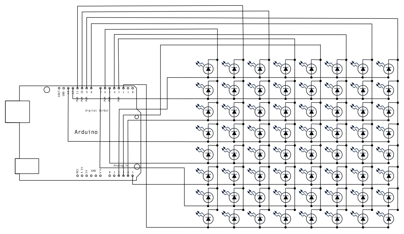
虽然有预先制作好的LED矩阵,你也可以用64个LED灯制作一个属于你自己的矩阵。原理图如上面:
-
哪一个微控制器的引脚连接到行和列都没有关系,因为你能在软件里设置这些东西。尽量用一种简单点的方式连接引脚。一个典型的排版如下。
-
这里是一个基于上面原理图的矩阵引脚连接表:
|
Matrix pin no. |
Row |
Column |
Arduino pin number |
|
1 |
5 |
- |
13 |
|
2 |
7 |
- |
12 |
|
3 |
- |
2 |
11 |
|
4 |
- |
3 |
10 |
|
5 |
8 |
- |
16 (analog pin 2) |
|
6 |
- |
5 |
17 (analog pin 3) |
|
7 |
6 |
- |
18 (analog pin 4) |
|
8 |
3 |
- |
19 (analog pin 5) |
|
9 |
1 |
- |
2 |
|
10 |
- |
4 |
3 |
|
11 |
- |
6 |
4 |
|
12 |
4 |
- |
5 |
|
13 |
- |
1 |
6 |
|
14 |
2 |
- |
7 |
|
15 |
- |
7 |
8 |
|
16 |
- |
8 |
9 |
硬件要求
- Arduino or Genuino开发板
- 8 x 8 LED 矩阵
- 2 10k ohm电位计
- 连接线
- 面包板
电路
-
矩阵的16个引脚连接到Arduino或者Genuino开发板的16个引脚。4个模拟引脚被当作数字输入引脚16-19。引脚的顺序按代码里的2组数组来分配。
-
两个电位计,连接到模拟引脚pin0和pin1,控制矩阵的LED行动。
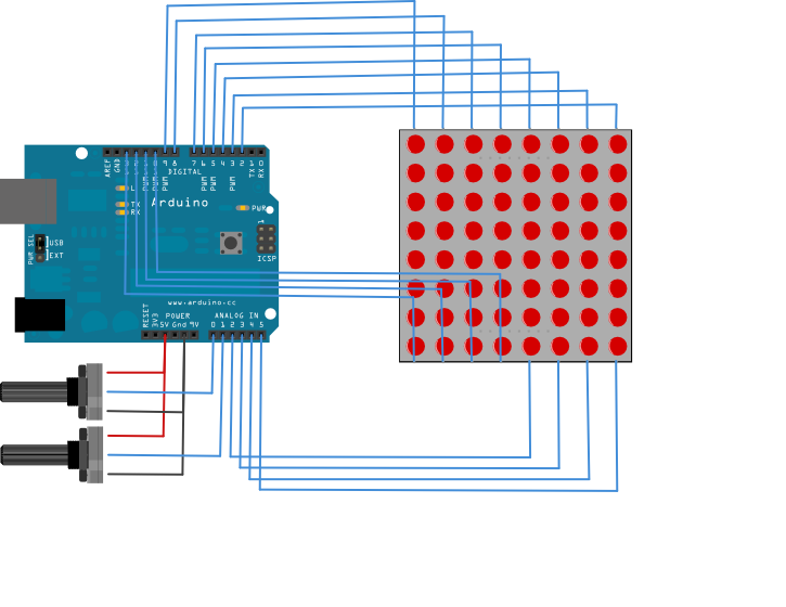
图由 Fritzing 软件绘制。
原理图
样例代码
/*
  Row-Column Scanning an 8x8 LED matrix with X-Y input

 This example controls an 8x8 LED matrix using two analog inputs

 created 27 May 2009
 modified 30 Aug 2011
 by Tom Igoe

 This example works for the Lumex  LDM-24488NI Matrix. See
 http://sigma.octopart.com/140413/datasheet/Lumex-LDM-24488NI.pdf
 for the pin connections

 For other LED cathode column matrixes, you should only need to change
 the pin numbers in the row[] and column[] arrays

 rows are the anodes
 cols are the cathodes
 ---------

 Pin numbers:
 Matrix:
 * Digital pins 2 through 13,
 * analog pins 2 through 5 used as digital 16 through 19
 Potentiometers:
 * center pins are attached to analog pins 0 and 1, respectively
 * side pins attached to +5V and ground, respectively.

 This example code is in the public domain.

 http://www.arduino.cc/en/Tutorial/RowColumnScanning

 see also http://www.tigoe.net/pcomp/code/category/arduinowiring/514 for more
 */


// 2-dimensional array of row pin numbers:
const int row[8] = {
  2, 7, 19, 5, 13, 18, 12, 16
};

// 2-dimensional array of column pin numbers:
const int col[8] = {
  6, 11, 10, 3, 17, 4, 8, 9
};

// 2-dimensional array of pixels:
int pixels[8][5];

// cursor position:
int x = 5;
int y = 5;

void setup() {
  // initialize the I/O pins as outputs
  // iterate over the pins:
  for (int thisPin = 0; thisPin < 8; thisPin++) {
    // initialize the output pins:
    pinMode(col[thisPin], OUTPUT);
    pinMode(row[thisPin], OUTPUT);
    // take the col pins (i.e. the cathodes) high to ensure that
    // the LEDS are off:
    digitalWrite(col[thisPin], HIGH);
  }

  // initialize the pixel matrix:
  for (int x = 0; x < 8; x++) {
    for (int y = 0; y < 8; y++) {
      pixels[x][y] = HIGH;
    }
  }
}

void loop() {
  // read input:
  readSensors();

  // draw the screen:
  refreshScreen();
}

void readSensors() {
  // turn off the last position:
  pixels[x][y] = HIGH;
  // read the sensors for X and Y values:
  x = 7 - map(analogRead(A0), 0, 1023, 0, 7);
  y = map(analogRead(A1), 0, 1023, 0, 7);
  // set the new pixel position low so that the LED will turn on
  // in the next screen refresh:
  pixels[x][y] = LOW;

}

void refreshScreen() {
  // iterate over the rows (anodes):
  for (int thisRow = 0; thisRow < 8; thisRow++) {
    // take the row pin (anode) high:
    digitalWrite(row[thisRow], HIGH);
    // iterate over the cols (cathodes):
    for (int thisCol = 0; thisCol < 8; thisCol++) {
      // get the state of the current pixel;
      int thisPixel = pixels[thisRow][thisCol];
      // when the row is HIGH and the col is LOW,
      // the LED where they meet turns on:
      digitalWrite(col[thisCol], thisPixel);
      // turn the pixel off:
      if (thisPixel == LOW) {
        digitalWrite(col[thisCol], HIGH);
      }
    }
    // take the row pin low to turn off the whole row:
    digitalWrite(row[thisRow], LOW);
  }
}更多
- pinMode()
- for()
- digitalWrite()
- if()
- map()
- Writing Functions - 创建代码的模块来完成特定的任务
- For Loop Iteration - 用for循环控制多个LED灯
- Arrays - 在For循环例子里的一个变量,示范了怎么使用一个数组。
- If Statement - 怎样用一个if声明来实现改变输入会改变输出的目的。
- LED Bar Graph - 控制一个8×8的LED矩阵
Arduino playground有更多复杂的例子。其他例子可以在Tom Igoe's blog找到:
纠错,疑问,交流: 请进入讨论区或 请点击进入页面,扫码加入微信群或Q群进行交流
获取最新文章: 扫一扫加入“创客智造”公众号