


Arduino库教程-SPI-Digital Pot Control
纠错,疑问,交流: 请进入讨论区或 请点击进入页面,扫码加入微信群或Q群进行交流
获取最新文章: 扫一扫加入“创客智造”公众号
Controlling a Digital Potentiometer Using SPI
-
在本教程中,您将学习如何使用串行外设接口(SPI)来控制AD5206 数字电位器。更多解释看到the SPI Library reference。
-
当你需要用电而不是用手来改变电路中的电阻时,数字电位器是有用的。示例应用包括LED调光,音频信号调节和音频生成。在这个例子中,我们将使用一个六通道的数字电位器来控制六个LED的亮度。我们覆盖SPI通信的步骤可以通过使用其他SPI器件来改进。
硬件要求
- Arduino or Genuino board
- AD5206 数字电位器
- 6 LEDs
- 6 220 ohm 电阻
- 连接线
- 面包板
AD5206数字电位器介绍
点击获得 AD5206的数据手册
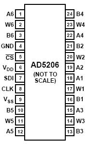
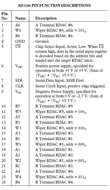
- AD5206 是一个6通道数字电位器。这就意味着有六个可变电阻(电位器)内置在个人电子控制。有六个内部可变电阻的三引脚芯片,他们可以与你会使用一个机械电位器。独特的可变电阻引脚标记为AX,BX和Wx,即A1、B1和W1。例如,在本教程中,我们将用每个可变电阻作为一个电压分压器,把一个引脚(引脚B)拉高,另一侧引脚(引脚A)拉低,并采取可变电压输出的中心引脚(Wiper)。在这种情况下,该ad5206提供一个最大值10K欧姆的电阻,分为255个等级(255是最大,0最小)。
电路
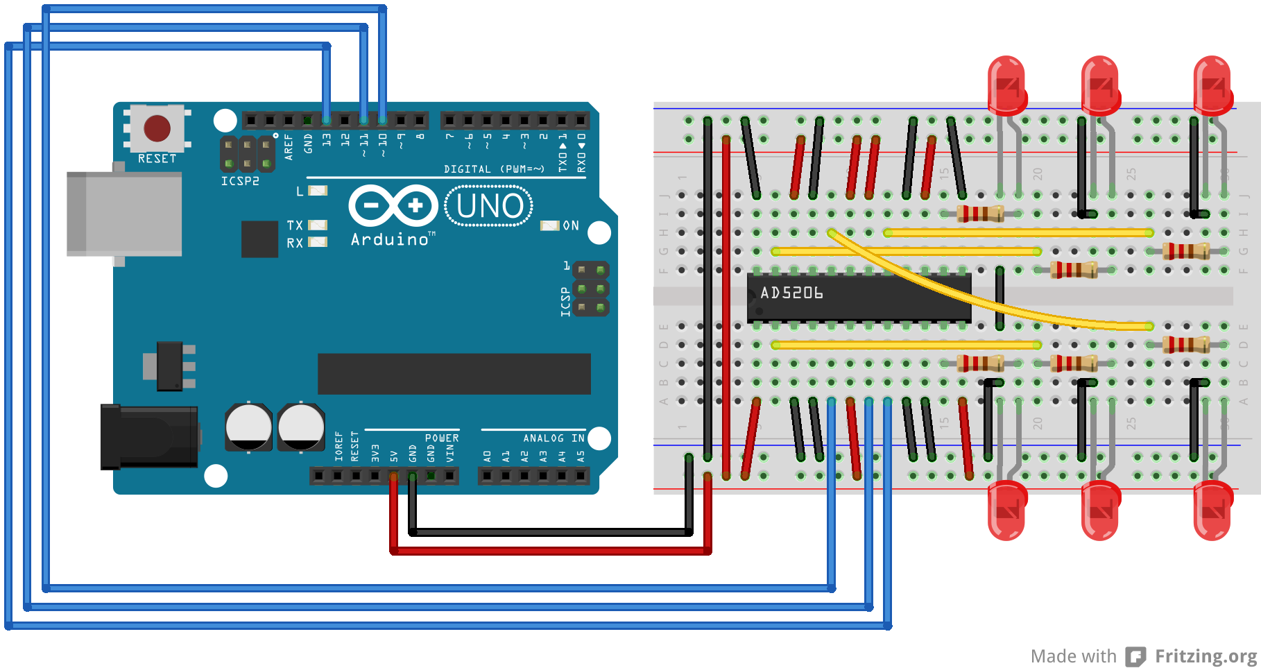 图由 Fritzing 软件绘制
原理图

样例代码
/*
  Digital Pot Control

  This example controls an Analog Devices AD5206 digital potentiometer.
  The AD5206 has 6 potentiometer channels. Each channel's pins are labeled
  A - connect this to voltage
  W - this is the pot's wiper, which changes when you set it
  B - connect this to ground.

 The AD5206 is SPI-compatible,and to command it, you send two bytes,
 one with the channel number (0 - 5) and one with the resistance value for the
 channel (0 - 255).

 The circuit:
  * All A pins  of AD5206 connected to +5V
  * All B pins of AD5206 connected to ground
  * An LED and a 220-ohm resisor in series connected from each W pin to ground
  * CS - to digital pin 10  (SS pin)
  * SDI - to digital pin 11 (MOSI pin)
  * CLK - to digital pin 13 (SCK pin)

 created 10 Aug 2010
 by Tom Igoe

 Thanks to Heather Dewey-Hagborg for the original tutorial, 2005

*/


// inslude the SPI library:
#include <SPI.h>


// set pin 10 as the slave select for the digital pot:
const int slaveSelectPin = 10;

void setup() {
  // set the slaveSelectPin as an output:
  pinMode(slaveSelectPin, OUTPUT);
  // initialize SPI:
  SPI.begin();
}

void loop() {
  // go through the six channels of the digital pot:
  for (int channel = 0; channel < 6; channel++) {
    // change the resistance on this channel from min to max:
    for (int level = 0; level < 255; level++) {
      digitalPotWrite(channel, level);
      delay(10);
    }
    // wait a second at the top:
    delay(100);
    // change the resistance on this channel from max to min:
    for (int level = 0; level < 255; level++) {
      digitalPotWrite(channel, 255 - level);
      delay(10);
    }
  }

}

void digitalPotWrite(int address, int value) {
  // take the SS pin low to select the chip:
  digitalWrite(slaveSelectPin, LOW);
  //  send in the address and value via SPI:
  SPI.transfer(address);
  SPI.transfer(value);
  // take the SS pin high to de-select the chip:
  digitalWrite(slaveSelectPin, HIGH);
}原教程由 Heather Dewey-Hagborg 制作, 由 Tom Igoe 和 Christian Cerrito 更新
更多
- Arduino SPI LIbrary - SPI库的参考网页
- BarometricPressureSensor - 用SPI来读取一个气压传感器。
纠错,疑问,交流: 请进入讨论区或 请点击进入页面,扫码加入微信群或Q群进行交流
获取最新文章: 扫一扫加入“创客智造”公众号