


Pixhawk无人机教程-3.1.6 Using the Relay Switch *
纠错,疑问,交流: 请进入讨论区或 请点击进入页面,扫码加入微信群或Q群进行交流
获取最新文章: 扫一扫加入“创客智造”公众号
Using the Relay Switch
You can use the onboard relay switch of APM 1 to control on/off devices that consumer more current than can be supplied by simply turning a digital pin on and off.
The way the relay works is that it switches between connecting a common center pin to one of the two outer pins (State 1 or State 2). So if, for example, you wanted to trigger a solonoid, you’d connect the solonoid’s V+ pin to the center pin, and connect State 1 to APM’s V+ and State 2 to Ground. In State 1, the solonoid would go on; in State 2 it would go off.
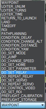
You script it into missions with any GCS. Here are the commands in the Mission Planner:
 Here’s some code that demonstrates it switching from one position to another.
pinMode(RELAY_PIN,OUTPUT);
while(1)
	delay(3000);
	Serial.println("Relay Position A");
	PORTL |= B00000100;
	delay(3000);
	Serial.println("Relay Position B");
	PORTL ^= B00000100;
纠错,疑问,交流: 请进入讨论区或 请点击进入页面,扫码加入微信群或Q群进行交流
获取最新文章: 扫一扫加入“创客智造”公众号