


Pixhawk无人机教程-6.12 相机安装 Camera mount
相机安装 Camera mount
相机的安装
ArduCopter 可以使用任何空余的输出通道平衡一个三自由度的云台,也可以把自稳和驾驶员的操作相结合(一般使用通道6的旋钮)。
A camera’s shutter can be triggered from the APM once connected with a servo or “relay”. The act of triggering the shutter can be controlled through your receiver’s channel 7 switch or automatically during missions.
警告: 请勿连接RC10和RC11的电源(红+黑-)到伺服系统,只使用信号线。使用PWM波输出接口的电源驱动伺服电机。这样可以避免由于伺服电机消耗太多电流而导致的APM掉电的情况。
通过地面站配置云台
在配置菜单,硬件选项中你可以找到相机云台设置界面。
For each servo/axis of your camera gimbal select the appropriate servo channel and ensure the “Stabilise” checkbox is checked.
The Servo Limits should be adjusted to ensure the gimbal servos don’t bind.
The Angle Limits should correspond to the tilt angle of the gimbal itself at the servo limits. If you find during testing that your gimbal is not properly remaining stabilised (for example it’s over or undercorrecting as you tilt the copter), adjust the angle limits up or down slightly.
(These are not really ‘angle’ limits but how much the servo is commanded to move within the limits of the 60° most servos can move.
eg If set to -60/+60 the servo will reach -30°/+30° (its limit) when the ‘copter reaches -60°/+60°
If set to -15/+15 the servo will reach -30°/+30° (its limit) when the ‘copter reaches -15°/+15°)
“Retract Angles” refer to the position of the gimbal when the mount’s mode is “retracted” (i.e. MNT_MODE=0). “Retracted” normally means when the gimbal is pulled into the body of the aircraft which is generally not relevant for multicopters.
“Neutral Angles” refer to the position of the gimbal when the mount is first initialised. This is normally facing straight forward.
“Control Angles” are parameters to allow control of the gimbal from a ground station perhaps using a joystick. These values are overwritten by the ground station so there’s no point in updating them on the MP screen.
If you find your gimbal is moving in the wrong direction, check the Reverse checkbox.

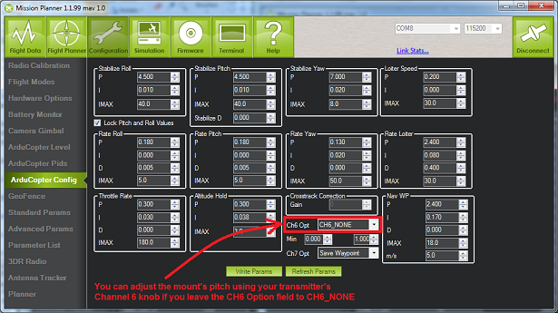
If you wish to adjust the gimbal tilt, roll or pan while flying, you can set the input channel to “RC6″ which normally corresponds to your transmitters tuning knob.
!Note! If you do this you need to set your CH6 Opt to “CH6_NONE” in the Mission Planner “Standard Parameters” -> “Configuration” screen.
Shutter configuration:
Warning: Do not connect power (red + & black -) from the A10 & A11 connectors to the servos, just use the servo signal lines. Power the servos via PWM Outputs connector or separate UBEC. These solutions will avoid the scenario that can possibly happen when the servo/s draw too much current and cause the APM to brownout (reset)
From ArduCopter version 2.9, a servo or relay can be controlled to press the camera’s shutter (or operate the servo to release a parachute) at a waypoint with the DO_SET_SERVO command (between two waypoints).
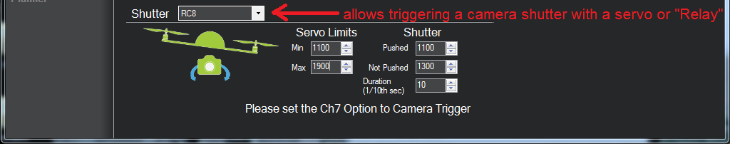
Use the Shutter drop-down (see image below) to select which analog output the servo is connected to, typically A10 or A11 (Not the channels, but the Analog outputs from APM, although the Mission Planner calls them RC10 and RC11 – check the photos in the Connecting Servos section below as to which is A10 & A11). Remember also a DO_SET_SERVO command must be placed between two waypoints.
Set up the Servo Limits so that the servo does not bind. Under “Shutter” you can set the PWM values (normally between 1000 ~ 2000) that correspond to the servo positions when the shutter is “pushed” and “not pushed”.”
(If you select “Relay” from the drop-down, then pin A9 on the APM2 will be pulled high to trigger tha camera’s shutter.)
The “Duration” field controls how long the servo pressing the shutter button remains held down. 10 = 1 second, 20 = 2 seconds, etc.
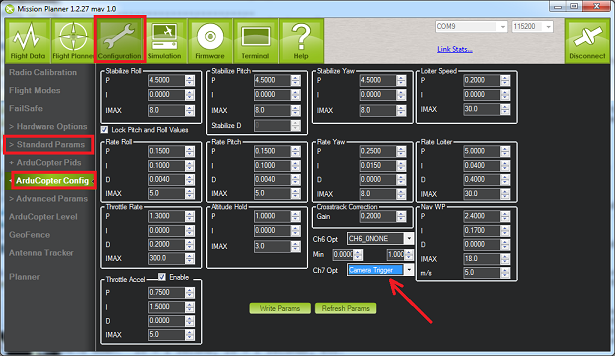
You can manually test that the shutter is being activated correctly if you set the the CH7 option (in Arducopter PID tab) to “Trigger Camera”, having set the “Shutter” to A10 and the limits in the previous step.
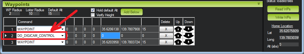
You can also trigger the servo during a mission using the “DO_DIGICAM_CONTROL” command (no additional parameters required).
Please note that like all other DO_x commands it cannot appear right at the beginning or end of a mission, it must be appear between two waypoints.
Panoramic Mode
In order to take panoramic pictures, you can force the copter to stay in place and rotate (yaw) on it’s axis.
Set the CIRCLE_RADIUS parameter to zero.
If you select CIRCLE mode during flight (or execute LOITER_TURNS during missions) the copter will stop and rotate in place instead of flying in a circle.
If the copter rotates too slowly you can adjust the CIRCLE_RATE from it’s default 5deg/sec to 10 or more.
You can attach a servo to your camera’s shutter and then you can configure it so that the servo fires when you switch the channel 7 (or channel 8) switch or when the DO_DIGICAM_CONTROL mission command is executed as described previously.
Connecting-the-servos-with-APM2">Connecting the servos with APM2
Warning: Do not connect power (red + and black -) from the RC10 (A10) and RC11 (A11) connectors to the servos.
Use the signal lines of the RC10 (A10) and RC11 (A11) connectors only.
Power the servos via the PWM Outputs connector power and ground pins.
Alternatively if you have digital servos you can assign the gimbal roll/tilt to RC5 to RC8 outputs, if they are free.
These solutions avoid the possibility that the Pan/Tilt servos can draw too much current and cause the APM to brownout and (reset).
Warning!! The illustration below shows the 2 sets of pads at the connector 12 and 13 positions as being unpopulated.
Your APM may have a longer connector which contains these pins as well.
Make sure to connect to pins 10 and 11 and NOT to pins 12 and 13 (marked NC for “Not Connected”).
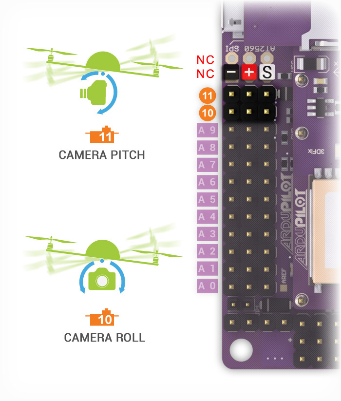
Note: APM2.x RC10 & RC11 outputs operate at 50hz (labeled A10 & A11 on the case) making them acceptable for analog or digital servos while PWM outputs RC1 to RC8 operate at 490hz making them theoretically only suitable for digital servos.
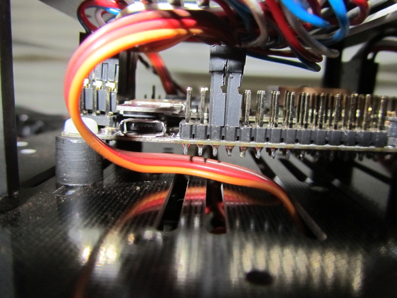
Here’s a photo to show the pitch/roll servo connectors plugged into outputs 10 and 11, (Note: they are the 3rd and 4th set of pins from the left in this picture):
PX4 Camera Gimbal Servo Connection
The Camera Gimbal Servo connections are located on (FMU USART2) on the PX4IO board.
The 5 pin connector on the end of the PX4IO board opposite the servo connector and at the edge of the board.
The roll camera gimbal servo out signal wire should connect to pin 2 (RC9).
The pitch camera gimbal servo out signal wire should connect to pin 3 (RC11).
If you have a yaw camera gimbal it’s servo out signal wire should should connect to pin 4 (RC12).
Provide power and ground separately to the servos.
Tuning for Problems Relating to Camera Usage
The “jello” effect (or rolling shutter) is a by-product of using a camera with a CMOS sensor (GoPro, et al) caused by vibration from unbalanced props/motors and can be mitigated by mounting the camera on soft rubber, silcone, foam ear plugs or sometimes just on velcro.
If you have jerky camera movement out it may also be that your MultiCopters Rate PID P value is set too high.
The primary symptom of too high a Rate P value is a 5 to 10 hertz oscillation.
Generally high performance MultiCopters (With a high thrust to weight ratio) will require a lower Rate P value to avoid oscillation.
For Video use, even a Rate P value that does not visibly seem to cause oscillation when looking at the copter can still cause it to oscillate sufficiently to produce the “jello” effect on the video.
Try lowering the P value by 30 percent or so.
获取最新文章: 扫一扫右上角的二维码加入“创客智造”公众号