


Pixhawk无人机教程-6.10 External Magnetometer for Improved Performance *
External Magnetometer for Improved Performance
Using an External Magnetometer
Note! You may alternatively use the combination GPS / Compass module, the Installation of which is covered (Here!)
If you’re having trouble with magnetic noise affecting your compass on-board the APM 2.5 board, you may want to switch to an external compass that you can mount further away from noise sources such as motors and your power wiring and batteries.
Magnetometers are most strongly influenced by DC magnetic fields and your batteries and the ESC primary power wiring are the worst offenders.
Your primary goal is to distance the magnetometer from batteries, DC battery wiring and the wiring to your ESCs.
It will also help to twist the battery and ESC power and ground wires wires together where possible.
It is also important to keep the magnetometer distanced from magnetic metallic objects (use nylon or non magnetic stainless screws and hardware in it’s vicinity and use aluminum or nylon standoffs.).
The GPS antenna should always be on top (facing Up).
Note: If the Magnetometer board is mounted in its correct direction (arrow forward) and the Flight controller board is also mounted upright arrow forward, the (COMPASS_ORIENT) parameter will need to be set to (Normal) or “0″.
Note: You will need to set the Magnetometer Orientation Parameter (COMPASS_ORIENT) in the Mission Planner Advanced Parameter List correctly to accommodate the Magnetometer’s orientation.
Note: If the Flight controller board is used in an alternate orientation (or upside down), the (COMPASS_ORIENT) parameter will need to also be adjusted to accommodate the Flight controller boards orientation as well as it’s own. (They are additive).
Step-by-step-instructions-for-APM-2.5<-strong>">Step-by-step instructions for APM 2.5
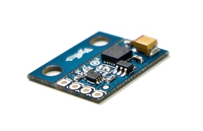
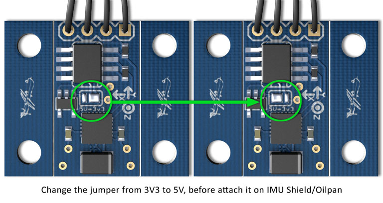
Purchase a HMC5883L magnetometer breakout board. Make sure the 3DR board is set to use 3.3volts (the APM 2.5’s I2C port uses 3.3 volts, not 5 volts). You will have to modify the 3DR board because it is shipped from 3DR with the 5 volt jumper set, as shown below.
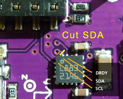
Looking at the below picture, cut the jumper trace in the middle of the APM 2.5 board. This disables the SDA line to the board’s internal magnetometer, rendering it inert.

The APM 2.5 I2C connector needs a 4 pin DF13 connector, such as this one. Cut off one and and strip and tin the four wires.
Connect the DF13’s 4 wires to the compass breakout board. Note that the wires will not be one to one. Pin 1 on the DF13 connector will not go to pin 1 of the compass board. The standard 3DR cable has one red wire and three black wires. Substitute your wire colors accordingly. Solder the wires as follows:
Red wire
on end of connector (+3.3v) goes to the VCC (or +3.3v) pad on the compass board (see labels on board for location). This is the wire closest to the interior on the APM 2.5 board.
Wire next to red wire
(SCL) goes to the SCL pad on the compass board.
Wire next to wire next to red wire
(SDA) goes to the SDA pad on compass board.
Black wire on end of connector
(ground) goes to ground pad on compass board. This is the wire closest to the edge of the APM 2.5 board.
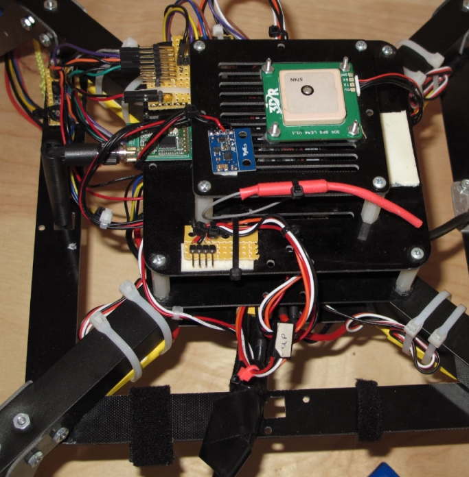
- The photo below depicts a MultiCopter with the Magnetometer mounted on top away from the DC magnetic fields generated by the Power Wiring and ESCs.
Double-sided foam tape works well for this.
The GPS modules antenna must be on top.
In the picture below, we’ve mounted the board “components up with pins forward”.
Flight controller board orientation and magnetometer orientation must be used to calculate the COMPASS_ORIENT parameter.
INSTRUCTIONS FOR THE APM 2.0
The APM 2.0 requires the cutting of the SDA trace on the top of the GPS / Magnetometer / SDA carrier board.
Also, leave the pads on the external Magnetometer board bridged for 3.3 volts rather than switching it to 5 volts..
The remainder of the procedure is exactly as explained for the APM 2.5.
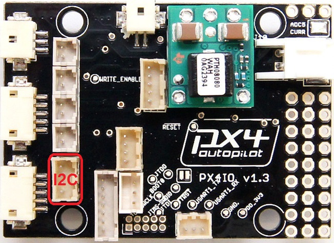
INSTRUCTIONS FOR THE PX4
The PX4 does not require any modifications to the PX4 boards at all.
When the external Magnetometer is plugged into the PX4IO boards I2C port it is automatically detected and used and the internal one is disabled.
The PX4IO boards I2C port is the 4 pin connector located on the board side opposite the Servo Out connectors in the second row of connectors in and next to the board mounting hole.
获取最新文章: 扫一扫右上角的二维码加入“创客智造”公众号