


Pixhawk无人机教程-6.14 相机自稳 Automatic Camera Stabilization
相机自稳 Automatic Camera Stabilization
Automatic Camera Stabilization
This page is for those that want to use their Pan/Tilt Gimbals to keep their FPV video feed/s from wobbling around when the airframe does, or who want to take imagery of the ground from directly overhead ( eg surveying).
It is sometimes also called “Earth-frame picture stabilization” but this simply means “keep the camera level, irrespective of the tilt/roll of the aircraft ( plane or quad)”.
See the Tracking page for other Camera options like Position Tracking and Remote Shutter Triggering.

Camera Angle/s
Vertical will give the looking straight down viewpoint photo and is a good place to start. More dramatic viewpoints and often more recognizable can be achieved with angles other than vertical.
Mount about 40 degrees deviation from vertical to obtain mainly ground photos but with oblique view. About 70 degrees off vertical will give you a lot more sky giving scenic photos (from Draganfly).
Your decision here is unimportant to the software, as the software job is to maintain the gimbal angle to your programmed state, no matter what that is.
Typical gimbals are just a level platform onto which you can attach your camera/video device at whatever angle you like.
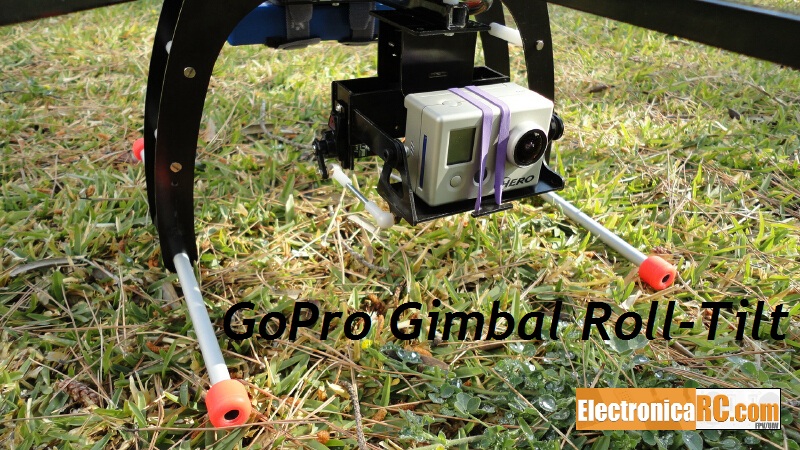
Camera Mount Build
The camera needs to be mounted securely to the gimbal and yet it also needs to dampen vibrations from the motor.
It is difficult to achieve both aims at the same time. The many ways that the flying community has used to mount the camera on the gimbal include: soft foam, stiff foam, neoprene tubes (mount camera on tube side), surgical tube, rubber bands, nylon bolt (direct stiff attachment) and velcro. Tubes have been used mostly on helis.
We make no specific recommendation here as the best or easiest has still to be decided and also depends on the airframe.
Even so, velcro plus rubber bands (for extra security) is quick to set up and will give you reasonable results.
Connecting the Gimbal servos
Connect your roll, pitch and yaw(optional) servos to any the APM auxiliary servos outputs (we will tell the software what’s on which channel later, in the setup process)
For APM 1: ch5, ch6, ch7 and/or ch8
For APM 2.x: ch5, ch6, ch7, ch8, ch9, ch10 and/or ch11 (Note ch9, ch10 & ch11 have a factory trace connecting to the correct digital out pin for servo or relay).
For the APM 2.x board for ch9, ch10 and/or ch11 ensure that the jumper trace(s) on the bottom of the board have not been cut and that they have not been re-jumpered for analog use.
You can connect them in any order you like. If you do not have or use one of them just do not connect it. You can also connect one servo to open/close the camera or to deploy/retract the camera and a servo to trigger the camera.
eg: connect roll/tilt servo’s to output channels tilt( 6) , roll ( 5) .
Software Setup Steps:
Power your APM and connect it to the Mission Planner software.
In the HARDWARE -> Optional Hardware -> Camera Gimbal window, map the channels that you just connected by setting the respective RC channel into the Tilt/Roll/Pan drop-down box/s.
eg: select Tilt=>RC6 and Roll=>RC5 in the gimbal page of planner ( do not select anything for pan unless you have one attached, leave it blank.)
Leave the “Input Ch” fields as “Disable”, this is important for maintaining a level gimbal irrespective of the RC channel information.
Wiggle the airframe ( APM) around a bit, and the servo/s should all move at this point ( probably wrongly, but that’s OK).
check servo’s move the correct direction to keep servo horn stationary relative to ground when airframe is moved, and if not, tick the “reverse” box where required. ( if the wrong servo moves, you just need to redo the earlier step where you assigned the (eg) “tilt” to RC6, and instead assign it to (eg) RC5.
select initial Min and Max values of 900 and 2100 ( which is deliberately outside of the range of the servos) in selection boxes, for both tilt and roll.
determine max “throw” of gimbal hardware in all 4 directions, we’ll assume it can physically go 45deg in every direction for this example.
set Min and Max Angle limits to -45 and 45 ( initially at least) to reflect the maximum physical throw limits of the gimbal

Aligning Min and Max PWM values with full throw of gimbal:
tilt airframe over hard left ( just past where the servo stops moving, or ~45 deg ), and raise the “Roll” “Servo” “Min” value until the servo starts to physically move a tiny bit, stop there.
tilt airframe over hard right ( just past where the servo stops moving, or ~45 deg ), and lower the “Roll” “Servo” “Max” value until the servo starts to physically move a tiny bit, stop there.
Repeat for Pitch ( forward and backward motion)
Leveling/Centering the gimbal :
keep the airframe perfectly straight-and-level
if the gimbal is not quite perfectly level, tweak the hardware first, eg, get servo horn/s so that gimbal is as close to level as possible before doing next step/s .. do this by unscrewing horn from servo and repositioning it, and/or if using push-rods to the gimbal, by adjusting the length of them).
If “tilt” is still not quite level, you can “trim” it by adjusting the Tilt->Angle->Min and Tilt->Angle->Max … BOTH by one click in the same direction ( eg, click both down arrows once each) This will ensure that the difference between them remains constant ( important ), but will adjust the “centre” position of the gimbal by small amounts ( do not do this too much as it affects the maximum throw/s at the extremeties by the same amount).
获取最新文章: 扫一扫右上角的二维码加入“创客智造”公众号