


Pixhawk无人机教程-3.1.5 Vibration Damping
纠错,疑问,交流: 请进入讨论区或 请点击进入页面,扫码加入微信群或Q群进行交流
获取最新文章: 扫一扫加入“创客智造”公众号
Vibration Damping
Vibration Damping and Isolation of the Flight Control BoardsWhy Vibration Damping and Isolation:Three Quick Fix (tested adequate) Solutions:Gel Pad Mount:O-ring Suspension Mount:Ear Plug Mount:Additional Vibration Reduction ConsiderationsProduce your own Accel Graphs to Evaluate your Vibration Control SuccessVibration Damping and Isolation for MultiCoptersEven More Considerations Relating to Vibration Control参考手册目录
Vibration Damping and Isolation of the Flight Control Boards
Why Vibration Damping and Isolation:
The APM or PX4 Flight Control boards have accelerometers and gyros built into the board that are sensitive to vibrations.
The latest release of the ArduPilot firmware uses the built in Accelerometers for position maintenance (Inertial Navigation).
It is necessary for us to reduce vibration below plus and minus one half G and it is even better if we can get below two tenths G.
The techniques presented here will work with both the APM series, cased and uncased and the PX4 flight controller systems.
Three Quick Fix (tested adequate) Solutions:
Each of these techniques can achieve flight logged Accel values of less than + or – 2 (2/10 G).
Gel Pad Mount:
The easiest solution uses off the shelf gel vibration damping pads of appropriate size on each corner of the flight control board.
Check out this great video that clearly illustrates the value of Gel Vibration isolation using Moon Gel (Kyosho Zeal is nearly identical): (Here!)
Kyosho Zeal Gel double sided tape, or 30 durometer Sorbothane are a workable solution at this time so long as you use small enough pieces of them.
Kyosho Zeal Tape Link: (Here!) Gelmec Silicone Grommets Link: (Here!) Gelmec Silicone Pads Link: (Here!) Sorbothane Company Link: (Here!) Sorbothane 30 durometer 3/16″ x 12″ x 12″ sheet Link: (Here!)
Moon Gel and Alpha Gel can also be used effectively in the same way as the Kyosho Zeal Gel. Simply putting a double sided taped pad under the entire board as has been common is entirely inappropriate for optimal vibration isolation because the mass of the flight control board is so small.
You should use pads of damping material 1/2″ to 1″ square on each corner of the board or APM enclosure box. (smaller for the bare board than the board in the enclosure), obviously.
Because the pads are so small you may want to put some sort of retaining (strap) over the whole thing. But if you do, it should not interfere with the damping of the pads.
The best method of retaining the flight controller is a Velcro Strap with 1/4 to 1/2″ of soft foam between the strap and the flight controller tightened so as to apply only light pressure Alternatively, a rubber band lightly stretched over the top of the board and looped over frame mounted screws on each side can actually aid the damping characteristics provided it does not exert too much pressure.
 FlameWheel F330 with Kyosho Zeal Pads
 FlameWheel F330 With PX4 Mounted on Intermediate platform
 FlameWheel F330 With PX4 on Zeal Pads with Protective Hard Top
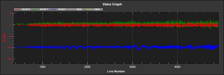
 The Zeal Mounted FlameWheel has Plus and Minus one vibration all axes = 1/10 G
O-ring Suspension Mount:
Another workable solution requires that you mount 4 standoffs on the top of your !MultiCopter such that the standoffs are between 1/10″ and 1/8″ directly outboard of each corner of the flight control board.
Warning! If you are mounting your flight control board to the power distribution board it might be better to mount the standoffs for the Flight control board to a separate piece of fiberglass cut to size that can subsequently be bolted through existing holes in the power distribution board. Only drill through the power distribution board for mounting the standoffs if you are completely certain you will not cause a short and use threaded nylon machine screws or standoff studs.
You can then insert 1/16″ (material diameter) O-rings through each corner of the flight control board and place both loops of the O-ring over a machine screw protruding from the top of each standoff. There should only be 1/10″ to 1/8″ of clearance from the board corners to the standoffs and the overall O-ring diameter should be chosen to firmly retain the board while providing for light to moderate initial but rapidly snubbed movement of the board (generally 1/2″ to 3/4″ OD) and Silicone O-rings should generally damp better than Buna-N O-rings if you can acquire them.
Link for Silicone or Buna-N O-rings Sizes 15 – 21 generally: (Here!)
Vibrations are short coupled, so all that leaving excess corner clearance does is to require higher initial O-ring tension which reduces vibration damping responsiveness and allows the board to physically tilt more (which is undesirable as it throws the sensor to airframe relationship off).
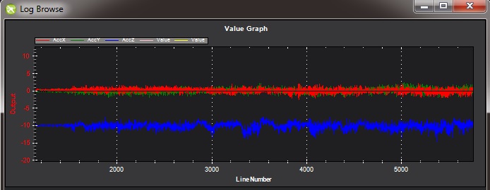
 FlameWheel F450 O-Ring Suspension Platform Mount Raw Accel Values
This mount reduces the vibration of this QuadCopter to about + and – 1 in all axes = 1/10 G.
 FlameWheel O-Ring Suspension Mount
Ear Plug Mount:
The third “Quick Fix” is a little more out there, but it definitely can be made to work effectively especially if you increase the mass of the flight control board by mounting it and your receiver on a separate fiberglass plate which is itself damped.
This vibration solution uses ear plugs pulled through air frame holes on one side and the flight control board / enclosure / backing plate on the other leaving the center of the earplug between them. This is a very clever and quite successful solution with easy to obtain and inexpensive materials. Not every style or material of ear plug would work and clearly the individual design of the earplug and the material it is made out of are very important.
Silicone, Polyurethane Foam and PVC foam are all viable candidates.
Slow response urethane foam and silicone are probably superior to other foams for damping. You must ensure that the finished solution is strong enough to retain your electronics module during “rough landings” and minimize module free play while still providing adequate vibration damping. Keep the 4 ear plug holes as near the corners of your electronic module plate as possible to minimize unnecessary module movement.
Drill the holes sized appropriately to allow insertion of the ear plugs but to also provide tight retention of them.
De-burring the holes to keep them from cutting wouldn’t hurt either.
They do “set” into place once inserted.
Some variance in free play and damping characteristics can be achieved simply by varying the amount of earplug left exposed in the middle, so they can actually be “tuned”.
Manfred Dickgeisers illustration uses the earplugs on a hanging mount and he prefers that, but if the hole size and ear plug material are appropriately selected for the electronics module mass, top mounting work fine too.
Some ear plugs definitely worth trying are these by 3M using their EAR type slow response urethane foam which is also what they use in their vibration damping products.
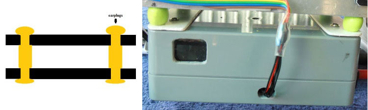
Ear Plug – vibration isolation diagram and photo of the box containing the APM and receiver suspended by the Ear Plugs.
!Note the extra mass of the box and receiver actually improve vibration damping and isolation.
 Ear Plug Vibration Damping Mounting Technique
Another excelent example of an Ear Plug Vibration reducing mount
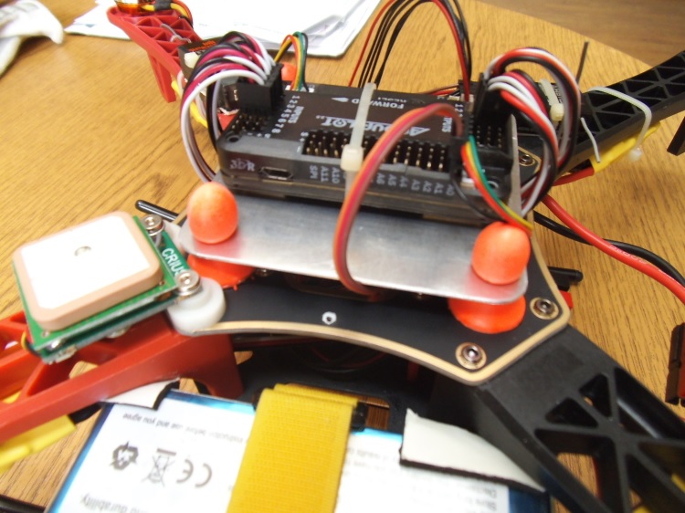 Ear Plug Vibration Mount
Additional Vibration Reduction Considerations
Significant gains in vibration isolation can also be realized by using a high flex wire and strain relief approach to all wires connected to the Flight control board (and using the minimum number of wires necessary as well.)
Isolation and damping can be improved somewhat by sandwiching the flight control board / enclosure between damping pads on both sides in about twenty percent compression. 30 durometer Sorbothane is actually specified at 15 to 20 percent compression for optimal damping.
A link to a Blog about the first APM anti-vibration mounting system to achieve 0.05 G damping (2/20/2013 improved to 0.02 G), a dual zone isolation system, combining Oring suspension and silicone pad: http://diydrones.com/profiles/blogs/very-good-anti-vibration-results-with-following-apm2-5-mount-quad
Propeller balancing is always a good idea and can significantly reduce the vibration transmitted to the airframe in the first place.
Propeller balancing is not covered in detail here because there are literally hundreds of references to it on line and it is fundamental to RC modeling. Google “RC Propeller Balancing”.
Motor balancing can also reduce vibration and especially so for cheaper or larger motors.
A quick and clever way to achieve satisfactory motor balancing:
Tightly fasten a small tie wrap around a motor (WITH NO PROP), trim off the extended tab and spin it up.
Try multiple times, each time turning the tie wrap on the motor housing a bit until the vibration reduces or goes away.
A small piece of Scotch tape can be re-positioned instead of the tie wrap if desired or for smaller motors.
When you locate the spot where there is the least vibration (and you should be able to hear it), mark the spot directly under the clasp of the tie-wrap with a felt pen.
Add a small dot of hot glue gun glue where the Tie-Wrap clasp was and increase the glue a bit at a time till the vibration is minimized.
If you put too much glue on it can be removed with an X-acto knife. – Simple but effective. Vibration Damping added at the motor mounts can significantly reduce vibration at the airframe, but the vibration damping method and hardware must be matched to the size and performance of your multicopter.
Link to a really good vibration damping motor mount: (Here!)
SteadiDrone Has a unique motor damping solution and their Quad airframe at $335.00 is very high quality: (Here!)
Camera Mounts also need to be effectively isolated and damped from vibration, but they already have a number of “soft” mounting solutions.
Just remember that your servos need to be vibration isolated as well, either in the isolated camera mount itself or with their own vibration reduction solution.
You should use high quality ball joints on your camera servo arms and adequate bearings or bushings in the mount itself with zero free play to prevent inertial slop.
Quality servos without free play are also a must for precision camera work.
Produce your own Accel Graphs to Evaluate your Vibration Control Success
Perform a test flight and generate a flight log of accelerometer data which you can display in Mission Planner.
In order to record the necessary Accelerometer data to your flight logs you will need to enable RAW mode in the “Log” recording function of the APM (which is off by default).
Hook up your APM to you PC with the USB cable. Start the Mission Planner Software on your PC. DO NOT select the connection icon but instead select Terminal mode. Type in “logs” and the enter key. Type in “enable raw” and the enter key. Raw Accelerometer and Gyro information for all 3 axes will now be recorded to the flight log that is produced each time you fly. Disconnect from the PC.
Test fly your MultiCopter and acquire an appropriate Flight Log.
Hook up your Copter to fly as you normally would. In calm winds make a short test flight. In stabilize mode arm the copter (this will begin recording of the flight log). Take off and hover a few feet off the ground. Fly for 30 seconds or so stably hovering then land. Disarm (very important to cause saving of recorded flight data.) Disconnect your battery and return to your computer.
Display the Accel information you just recorded in Mission Planner
Hook your APM up to your PC as before with the USB cable and start Mission Planner. DO NOT select the “Connection” icon but instead select Terminal mode. In Terminal mode select the “Download Logs” tab. When it displays a list of logs (may take a while) scroll down to the bottom log (the one you just recorded) and select it. Then select the “Download These Logs” item. Select “Exit”. Now select the “Browse Logs” tab. Select the log you just downloaded. You will be presented with a blank graph screen and several lines of text on the bottom of the screen. Scroll down to the first “RAW” item heading on the left column of the text. Click on the heading “RAW”. You will now see at the top of the text column headings for Gyro and Accel. Select the box to the right of “RAW” under the “ACCEL X” column. Select the “Graph This” box which will graph your accelerometers X displacement for the duration of your flight. Repeat the above for “ACCEL Y” and “ACCEL Z”.
Interpret your Flight Logs Accelerometer information.
It is probably advisable to just window a portion of the flight log graph with the mouse and click it to display a smaller selection from a stable portion of the flight. You will want to see the normal vertical excursions of the vibration present on the Accel axes so window accordingly. The vertical numbers on the left of the graph are (I believe) in meters per second / per second however, due to a fortuitous circumstance 9.8 meters per second per second is one Gravity so 10 vertical units may be reasonably interpreted as one G. Each vertical graph division is one tenth G. Your vibration amplitude is what is significant here and that should be clearly visible to you now. Keep in mind that the Accel Z axis is the vertical axis which will be offset by one G (or – 10) on the graphs scale. The 2 horizontal Accelerometer X and Y should be centered around 0. Your vibration amplitude is read relative to zero for the X and Y axes and relative to -10 for the vertical Z axis. Vibration amplitude should be taken as the excursion from the axis 0 offset point in either direction, thus + and – 5 for example. Since the Z axis is offset by gravity to – 10 a vibration amplitude from – 5 to – 15 would still be an amplitude of + and – 5. A vibration amplitude of + and – 5 as above would represent one half G.
Since most of our flying takes place well inside the + and – one G range and we are attempting to the movement of our airframe to determine location and level you can see that any vibration greatly interferes with this process.
The APM or PX4′s internal firmware filtering can extract sufficient data for inertial navigation from vibration excursions of less than 1/2 G (5 on our scale).
However, reducing the vibration amplitude of each axis even lower, possibly even below one tenth G is a worthy pursuit and will be rewarded with very stable horizontal and vertical position maintenance and smooth control.
Vibration Damping and Isolation for MultiCopters
With the advent of version 2.9 of Arducopter, inertial primary control for the Z axis was incorporated Soon it will also be introduced for the X and Y axes as well. Inertial control makes considerable use of the flight control boards accelerometers and for this reason it is necessary to now take vibration damping and isolation of the flight control board much more seriously.
Initial improvements can be made by balancing the props and motors. At this point in time it seems that the more rigid the frame the better because frame flex introduces undesirable mechanical delay (hysteresis) in translating motor induced actions to the centrally located flight control board. (Do NOT shock mount the motor Arms).
It is reasonable to somewhat vibration damp the motor mounts themselves because they are on one end of the mechanism.
However, the most significant vibration damping gains will be made by properly isolating and or damping the flight control board itself.
Until now vibration abatement has been simply by trial and error sticking on of Foam or Gel pads or using O-ring suspension of the board to outboard standoffs and yielding highly variable results. The acceptability of the outcome has been verified by flight performance and by checking the RAW ACCEL values in the APM flight log.
This trial and error approach has achieved acceptable to good results, but is by no means optimum. The crucial fact that we have not properly addressed is that the amount and type of damping medium needs to be carefully matched to the weight (mass) of the item we are trying to isolate as well as the frequency and amplitude of the vibrations we are seeking to damp.
In fact we are trying to isolate a flight control board that weighs less than 2 ounces and this is a very small mass.
Our current seat of the pants “solutions” are often designed for much larger masses and are not nearly as effective for the light mass of our flight control board as they ought to be. Virtually all off the shelf solutions (either pad or stud type) are designed for an isolated mass that would weigh at least 5 to 10 times what an APM or PX4 / IO board weighs for optimal effectiveness.
This includes all pre-made Sorbothane, Alpha gel, EAR, memory foam or other silicone or urethane gel or foam mounts as well as Lord Micro mounts.
Great link for Antivibration grommets (use the .3lb ones): (Here!) Excellent Link for Alpha Gel, Silicone and Sorbothane: (Here!) EAR 3M Company damping material: (Here!) Lord Micro Mounts: (Here!)
Even More Considerations Relating to Vibration Control
Eventually it would be very nice to have a solution actually “engineered” for exactly the conditions of our flight control boards.
Although the “Quick Fixes” listed above do provide useful remedies they are not optimal. A threaded stud or sleeve type mount gel mount properly designed for the mass of our flight control board or electronics module undergoing the stress’s of normal flight would be a much better long term solution.
And a system that could actually sandwich the flight control board / enclosure between two layers of appropriate damping material of appropriate size could be even better.
It is probably a good idea to mount the flight control board as well as the receiver and possibly a clear cover on a separate (vibration damped) mounting plate.
This would have the advantage of increasing the mass of the item we need to provide vibration reduction for to the point where more conventional and commercially available solutions such as threaded stud or sleeve isolators could be employed effectively.
It would also reduce the amount of transition wiring necessary by placing the receiver to flight controller wiring entirely within the damped mass.
It could also make the electronics system more modular and easier to work on. For now we can adapt the engineering specifications of the chosen materials to provide the Vibration damping and Isolation we need.
A Summary of the particular vibration characteristics we need to damp:
The vibration frequency and amplitude we primarily need to reduce is a characteristic of the motor / prop units turning at flight speed.
That is, it is a fairly high frequency with fairly low amplitude. This requires that we provide a short coupled damping and isolation range. The board itself does not need to have nor benefit from a range of motion that exceeds the amplitude of the vibration.
Because the board does not apply any force to the airframe, the only thing we need to be concerned with Damping / Isolating is the weight (mass) of the board itself plus the forces applied to it by airframe’s normal flight maneuvering.
Since excellent broad frequency range, high damping materials are available our biggest concern will be to use the proper amount of them to optimally damp our flight control board. (Too much is just as bad as too little.)
Combining the Flight control board and receiver onto a separate vibration damped electronics module “plate” or enclosure can increase the mass of the module making it easier to damp effectively as well as reducing the interconnecting wiring and making the whole system more modular.
I have used the concept of vibration isolation and damping somewhat interchangeably in this section.
Isolation is simple undamped (spring or rubber band support) which allows the movement of the isolated object largely separate from the containing object (Automobile spring for instance). Damping is the conversion of vibration into heat energy by a shock absorbing medium (Automobile shock absorber for instance.) Our ultimate goal here is to provide the most high and medium frequency reduction while still allowing low frequency actual board movement to take place in concert with the airframe with a minimum of delay. So realistically our methods embody both Damping and Isolation.
I have covered a lot of ground here, but this is at least a good start for designing some real world vibration solutions .
Here is a link to an excellent RC Groups page on Vibration Effects relating to a camera mount but germane for us too: (Here!) Here is a link to the DIYDrones “Discussion” and the responses relating to Vibration Control: (Here!) And here is the link to the DIYDrones BLOG about this Wiki Section on Vibration Control: (Here!) You can enter any comments and pictures / illustrations on this BLOG if you wish. I will include the most relevant of them in the Wiki:
纠错,疑问,交流: 请进入讨论区或 请点击进入页面,扫码加入微信群或Q群进行交流
获取最新文章: 扫一扫加入“创客智造”公众号