


Pixhawk无人机教程-6.3 用于APM and PX4的3DR Radio数传
纠错,疑问,交流: 请进入讨论区或 请点击进入页面,扫码加入微信群或Q群进行交流
获取最新文章: 扫一扫加入“创客智造”公众号
用于APM and PX4的3DR Radio数传
Using the 3DR Radio for telemetry with APM 2.x and PX4
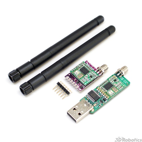
The 3DRobotics 3DR Radio
is the ideal way to setup a telemetry connection between your APM and a ground station. Small, inexpensive and with great range, the 3DR radio uses an open source firmware which allows us to do things that cannot be done with other radios.
Radio Features
very small size light weight (under 4 grams without antenna) available in 900MHz or 433MHz variants receiver sensitivity to -121 dBm transmit power up to 20dBm (100mW) transparent serial link air data rates up to 250kbps MAVLink protocol framing and status reporting frequency hopping spread spectrum (FHSS) adaptive time division multiplexing (TDM) support for LBT and AFA configurable duty cycle builtin error correcting code (can correct up to 25% data bit errors) demonstrated range of several kilometres with a small omni antenna can be used with a bi-directional amplifier for even more range open source firmware AT commands for radio configuration RT commands for remote radio configuration adaptive flow control when used with APM based on HM-TRP radio modules, with Si1000 8051 micro-controller and Si4432 radio module
Connecting your 3DR Radios
Important note:
You cannot connect via the radios when your APM 2.x is also connected via USB (they share the same port).
Make sure you disconnect your USB cable from the APM 2 board before attempting a wireless connection. You will need two 3DR radios, one for your aircraft, and the other for your ground station.
Looking at the above picture you will see that typically the “ground” radio module has a USB connector, making it easy to connect them to your ground station. It uses a D2XX FTDI driver that you can get
. This driver is built into Windows 7 and above, so it is only necessary if you are using Windows XP or below.
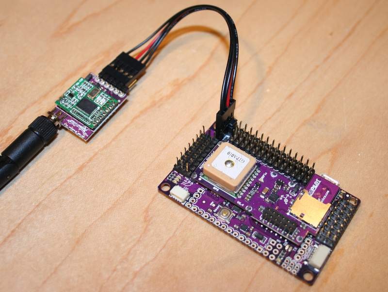
The ‘aircraft’ model has a FTDI six pin header, allowing it to be directly connected to your APM telemetry port.
For APM 2.5
Use the included cable:
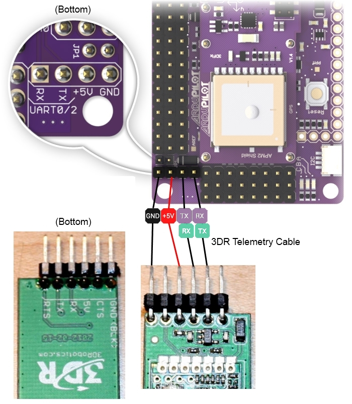
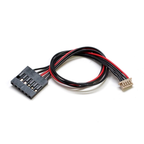 Plug it into the telemetry port on APM 2.5 and on the 3DR radio side, plug the connector with the red cable on the +5v pin and the black cable on the end on GND as shown:
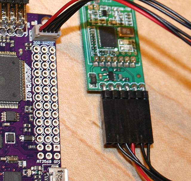
For APM 2.0
Connect the air modules to APM 2 as shown below:
The radios come pre-configured for a serial rate of 57600, which is the default rate that APM uses for telemetry, but you can change this to any rate you like, either using the AT command set, the APM Mission Planner radio setup interface, or the
3DR Radio Configuration Utility
PX4FMU plus PX4IO flight controller and the 3DR Telemetry Radio

Using the 3DR telemetry radio with your PX4FMU plus PX4IO Flight Controller.
You will need a 3DR radio (Here!) Plug the large black connector of the adapter cable into the 3DR radio remote as shown above.
The side of the black connector with the wire missing goes towards the center of the board.
Plug the adapter cable’s beige connector into the PX4IO FMU UART5 as shown above.
The FMU UART5 connector is on the opposite edge of the PX4IO from the Servo connector and is in the middle of the board.
Configuration and use of 3DR Telemetry Radio
Status LEDs
The 3DR Radios have 2 status LEDs, one red and one green. The meaning of the different LED states is as follows:
green LED blinking – searching for another radio green LED solid – link is established with another radio red LED flashing – transmitting data red LED solid – in firmware update mode
Configuring using the Mission Planner
The latest versions of the APM Mission Planner support configuring your 3DR radios using a simple GUI interface. In the Mission Planner (top right) select the Com port that your “ground” 3DR radio is connected to and 57k as the baud rate. Then press Control-A, and it will open this window. Click on “Load Settings” and it will populate it with data similar to that shown (the remote radio’s settings will only show if it is also powered on and connected to APM running current APM:Plane or APM:Copter code).
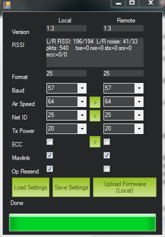
This is the recommended configuration method for most users.
Using a FTDI-to-USB cable to configure 3DR radios
If the previous paragraphs don’t work try the following… Connect everything, Configure 3DR ground radio
Connect your 3DR air radio with FTDI-to-USB cable to your computer USB port & note Com port #
Use Windows > Device Manager > Ports to identify com port # You’ll know the FTDI cable is correctly oriented on the air radio when a green LED blinks.
Connect the 3DR ground radio to a USB port on your PC & note Com port # * In MP Flight Data tab, at top right, set baud to 57600 & select ground radio com port # In MP Flight, press Ctrl + A to open the radio configuration window Click on Load Settings (from the ground radio) In Mission Planner radio configuration window, (MP) check the Advanced Options box If loaded values aren’t the same as above recommended settings, make it so, then click on Save
Configure 3DR air radio
In MP at top right, select the 3DR air radio’s com port In MP radio configuration window, click on Load Settings (from air radio)
Edit the air radio’s settings (including Advanced Options) so they are exactly the same as the ground radio’s, then click on Save Settings (to air radio)
You may not be able to add a value in the Format field, that’s OK
In Mp, press Configure > 3DR Radio > enter exact same settings including advanced > click Save Settings.
Wait for both radios to connect (solid green LED) Update firmware if above doesn’t work Click on Update Firmware while connected to each radio in turn. Then repeat the above. Keep in mind that while to are physically connected to a radio via a specific Com port, you can’t use the ‘Copy Required items to Remote’ button (there is no remote until you go wireless) To verify wireless telemetry
Remove the FTDI to USB cable from APM
Connect the air radio to APM & LIPO
In MP > Flight Data tab > select the ground radio com port then click on Connect
This section of the 3DRadio wiki was contributed by the Documentation User Group (DUG)
Serial and air rates ‘one byte form’
The SERIAL_SPEED and AIR_SPEED parameters are in the same form that APM uses for the SERIAL3_SPEED EEPROM parameter. It is the rate in kbps, truncated to an integer. So ’9′ means 9600 baud, ’38′ means 38400, ’115′ means 115200 etc.
Choosing the air data rate
The key parameter that controls the range of your radios is the AIR_SPEED. The default is 64 (which is 64kbps) will give you a range of over a kilometre with small omni antennas. The lower you set the AIR_SPEED the longer your range, although lowering the AIR_SPEED also lowers how much data you can send over the link.
The radio firmware can only support 13 possible air date rates, which are 2, 4, 8, 16, 19, 24, 32, 48, 64, 96, 128, 192 and 250. If your application needs a different air rate for some reason then we can potentially add it to the register tables. If you choose an unsupported air rate then the next highest rate from the supported list will be chosen.
What air data rate you choose will depend on the following factors
what range you need
what data rate you will be sending whether you primarily send in one direction, or both whether you have ECC enabled whether you have an APM firmware with adaptive flow control
For most telemetry applications you will primarily be sending data mostly in one direction, from the aircraft to the ground station. For most people, the amount of data sent from the ground station to the aircraft is small, just an occasional control packet plus heartbeat packets.
If you are using a joystick to control your aircraft then you will be sending a lot more data from the ground station to the aircraft, and in that case you may find a higher AIR_SPEED is needed, although your range will be reduced.
The ECC parameter makes a big difference to the data rate you can support at a given AIR_SPEED. If you have ECC set to zero, then no error correcting information is sent, and the radio uses a simple 16 bit CRC to detect transmission errors. In that case your radio will be able to support data transfers in one direction of around 90% of the AIR_SPEED.
If you enable ECC (which is highly recommended), then the data rate you can support is halved. The ECC system doubles the size of the data sent by the radios. It is worth it however, as the bit error rate will drop dramatically, and you are likely to get a much more reliable link at longer ranges. If you have the latest APM firmware (APM:Plane 2.33 or later, or APM:Copter 2.54 or later) then the APM will automatically adapt its telemetry rates to what the radio can handle, by using MAVLink RADIO packets injected into the MAVLink streams by the radios firmware. That allows you to ‘oversubscribe’ your link, by setting up a SERIAL_SPEED larger than what the radios can actually handle.
The other factor in choosing the air data rate is the TDM ‘sync time’. The two radios need to work out each others frequency hopping pattern. They do this by slowly changing the receive channel while rapidly changing the transmit channel. This process of getting in sync with the other radio takes just a few seconds at high air data rates, but gets slower for low air data rates.
For most amateur UAV applications the default AIR_SPEED of 64 with ECC enabled will be good.
Error Correction
As mentioned above, the radios support a 12/24 Golay error correcting code if you set the ECC parameter to 1. This means that for every 12 bits of data the radio will send 24 bits, calculating the bits using Golay code lookup tables. The process is reversed on the receiving end, and allows the radio to correct bit errors of up to 3 bits in every 12 bits send (i.e. 25% bit error rate).
The downside of the ECC option is that it halves your available data bandwidth, but in most cases this is worth it, as you are able to sustain a reliable link over longer ranges. You will also get a lot less ‘noise’ in the serial stream.
MAVLink framing
If you set the MAVLINK option to 1 then the radio will do ‘MAVLink framing’. The MAVLink protocol is used by APM for transmitting telemetry date to a ground station. When MAVLink framing is used, the radio will try to align radio packets with MAVLink packet boundaries. This means that if a packet is lost you don’t end up with half a MAVLink packet being seen by the receiver. That partial packet would appear as line noise on your ground stations console.
The radio firmware will try to fit multiple MAVLink packets into one radio packet where possible for maximum efficiency. The highest radio packet size is 252 bytes.
The radio firmware supports both the MAVLink 0.9 and the MAVLink 1.0 transmission formats.
MAVLink reporting
If you have MAVLINK set to 1, then the radio firmware will also look for MAVLink HEARTBEAT messages coming from the serial connection. If it sees a HEARTBEAT message then it knows that the MAVLink protocol is in use, and it will start injecting MAVLink ‘RADIO’ status packets into the the serial stream.
The RADIO packets contain information about the RSSI (Received Signal Strength Indicator) level at both ends of the link, allowing the ground station or aircraft to take action in case the link quality falls too low.
The RADIO packets also contain information about error rates, and how full the serial transmit buffer is (as a percentage). The latest APM firmware can use this information to automatically adapt the telemetry stream rates to the data rate that the radios can sustain.
Power levels
You need to be very careful to configure your radios to stay within the legal power limits of the country you are operating in. The default power level of 20dBm is fine for the US and Australia, as up to 30dBm is allowed by the LIPD class licenses there in the 915-928MHz frequency band for a frequency hopping radio. So as long as your antennas have a gain of less than 10dBi you should be within the ISM rules.
The radio cannot support arbitrary power levels. It can only support the power levels given in the following table
| Power (dBm)
|
Power (milliWatts)
|
| 1 | 1.3 |
| 2 | 1.6 |
| 5 | 3.2 |
| 8 | 6.3 |
| 11 | 12.5 |
| 14 | 25 |
| 17 | 50 |
| 20 | 100 |
If you choose an unsupported power level the radio will choose the next highest power level from the above table. Please carefully check the EIRP (Equivalent isotropically radiated power) power limits for your country, making sure you take into account the antenna gain. The 3DR radio is a ‘DIY’ radio part and it is entirely your responsibility to ensure any use of it is compliant with local rules. For example, if your local rules allow for a maximum of 30dBm (1W) EIRP, then if you use a amplifier with a 12dB transmit gain, and an antenna with 3dBi gain, then you will need to set TXPOWER to at most 14. If you don’t know how to calculate it, we’ve made a tutorial for you here:
Understanding dB, Watts and dBm
Using the AT command set
The 3DR radios support a variant of the Hayes ‘AT’ modem command set for configuration.
If you connect with a serial console to a 3DR radio at the current serial baud rate, you can tell the radio to enter AT command mode by entering the sequence ‘+++’. To prevent data being seen as the command sequence there is a guard time required, so make sure you type nothing on the serial link for 1 second before and after you enter the sequence.
When you enter AT command mode you will receive a ‘OK’ prompt from the radio and it will stop displaying data sent from the other radio.
Once in AT command mode, you can give the radio either ‘AT’ commands to control the local radio, or (if successfully connected) you can use ‘RT’ commands to control the remote radio. The AT commands available are:
ATI – show radio version ATI2 – show board type ATI3 – show board frequency ATI4 – show board version ATI5 – show all user settable EEPROM parameters ATI6 – display TDM timing report ATI7 – display RSSI signal report ATO – exit AT command mode ATSn? – display radio parameter number ‘n’ ATSn=X – set radio parameter number ‘n’ to ‘X’ ATZ – reboot the radio AT&W – write current parameters to EEPROM AT&F – reset all parameters to factory default AT&T=RSSI – enable RSSI debug reporting AT&T=TDM – enable TDM debug reporting AT&T – disable debug reporting
all of these commands, except for ATO, may be used on a connected remote radio by replacing ‘AT’ with ‘RT’.
Perhaps the most useful command is ‘ATI5′ which displays all user settable EEPROM parameters. That will produce a report like this:
 S0: FORMAT=22
 S1: SERIAL_SPEED=57
 S2: AIR_SPEED=64
 S3: NETID=25
 S4: TXPOWER=20
 S5: ECC=1
 S6: MAVLINK=1
 S7: OPPRESEND=1
 S8: MIN_FREQ=915000
 S9: MAX_FREQ=928000
 S10: NUM_CHANNELS=50
 S11: DUTY_CYCLE=100
 S12: LBT_RSSI=0
The first column is the S register to set if you want to change that parameter. So for example, to set the transmit power to 10dBm, use ‘ATS4=10′.
Most parameters only take effect on the next reboot. So the usual pattern is to set the parameters you want, then use ‘AT&W’ to write the parameters to EEPROM, then reboot using ‘ATZ’. The exception is the transmit power, which changes immediately (although it will revert to the old setting on reboot unless you use AT&W).
The meaning of the parameter is as follows:
FORMAT – this is for EEPROM format version. Don’t change it SERIAL_SPEED – this is the serial speed in ‘one byte form’ (see below) AIR_SPEED – this is the air data rate in ‘one byte form’ NETID – this is the network ID. It must be the same for both your radios TXPOWER – this is the transmit power in dBm. The maximum is 20dBm ECC – this enables/disables the golay error correcting code MAVLINK – this enables/disables MAVLink framing and reporting MIN_FREQ – minimum frequency in kHz MAX_FREQ – maximum frequency in kHz NUM_CHANNELS – number of frequency hopping channels DUTY_CYCLE – the percentage of time to allow transmit LBT_RSSI – Listen Before Talk threshold (see docs below)
For two radios to communicate the following must be the same at both ends of the link:
the radio firmware version the AIR_SPEED the MIN_FREQ the MAX_FREQ the NUM_CHANNELS the NETID the ECC setting the LBT_RSSI setting
the other settings may be different at either end of the link, although you will usually set them up the same at both ends.
Support for different countries/regions
It is very important that you find out what the local country or region regulations are on frequency, hopping channels and power levels and configure your 3DR Radios correctly for your local rules. Here is some general information to help you get started.
| Region
|
Radio Model
|
Settings
|
Standard
|
| USA | 3DR 900 | MIN_FREQ902000 MAX_FREQ928000 NUM_CHANNELS=50 | FCC 15.247 |
| Canada | 3DR 900 | MIN_FREQ
902000 MAX_FREQ 928000 NUM_CHANNELS=50 |
RSS-210 Annex 8.1 |
| Australia | 3DR 900 | MIN_FREQ
915000 MAX_FREQ 928000 NUM_CHANNELS>=20 |
LIPD-2000 item 52 |
| Australia | 3DR 433 | MIN_FREQ
433050 MAX_FREQ 434790 TXPOWER<=14 |
LIPD-2000 item 17 |
| Europe (most countries) | 3DR 433 | MIN_FREQ
434040 MAX_FREQ 434790 TXPOWER< 8 NUM_CHANNELS> 30 |
ETSI EN300 220 7.2.3 |
| Europe (most countries) | 3DR 433 | MIN_FREQ
433050 MAX_FREQ 434790 TXPOWER< 8 DUTY_CYCLE 10 |
ETSI EN300 220 7.2.3 |
| United Kingdom | 3DR 433 | MIN_FREQ
433050 MAX_FREQ 434790 TXPOWER< 8 DUTY_CYCLE 10 |
IR2030/1/10 |
| New Zealand | 3DR 900 | MIN_FREQ
921000 MAX_FREQ 928000 |
Notice 2007, Schedule 1 |
| New Zealand | 3DR 433 | MIN_FREQ
433050 MAX_FREQ 434790 |
Notice 2007, Schedule 1 |
| Brazil | 3DR 433 | MIN_FREQ
433000 MAX_FREQ 435000 TXPOWER<=8 |
252315&assuntoPublicacao null&caminhoRel In%EDcio-Biblioteca-Apresenta%E7%E3o&filtro 1&documentoPath |
| Brazil | 3DR 900 | MIN_FREQ
902000 MAX_FREQ 907500 NUM_CHANNELS>=11 |
Resolu??o ANATEL n?506/2008 |
| Brazil | 3DR 900 | MIN_FREQ
915000 MAX_FREQ 928000 NUM_CHANNELS>=26 |
Resolu??o ANATEL n?506/2008 |
We’d be delighted to add more countries to this table! Please post the information on the forums, giving links to the applicable regulations and information on what it all means. Also, please point out any inaccuracies in the existing table.
Note that the above table is for most users without any special license. If you are have an application specific license or have a HAM license then you should know what rules are applicable to you.
Finally, compliance is your responsibility. The 3DR radio is a ‘DIY’ radio part and you need to ensure what whatever you build meets local regulations. Please check your local rules carefully.
Available Frequency Ranges
The following table may be helpful matching your local radio regulations to the two radio models available
| Radio
|
Minimum Frequency (MHz)
|
Maximum Frequency (MHz)
|
| 3DR 433 | 414.0 | 454.0 |
| 3DR 900 | 895.0 | 935.0 |
Duty Cycle setting
Most users will want to set the DUTY_CYCLE to 100. The DUTY_CYCLE is the maximum percentage of time that the radio will transmit packets.
The reason the duty cycle is included is that some regions of the world allow for higher transmit power or more frequencies if you have a duty cycle below a given threshold. So for example in Europe you can transmit on a wider range of frequencies in the 433 band if your duty cycle is below 10%. When you set a duty cycle below 100% then your available bandwidth will be reduced, so you will find it will only work well for telemetry at higher baud rates. It is still quite practical to get good telemetry from an APM with a 10% duty cycle, as telemetry traffic is quite ‘bursty’, so the average transmit time is not generally high anyway.
For example, you can easily receive all telemetry streams at 2Hz with AIR_SPEED set to 128, ECC enabled and a DUTY_CYCLE set to 10.
You can also set a radio to receive only by setting the DUTY_CYCLE to 0. That will work best if you set NUM_CHANNELS to a low number, as otherwise the clock synchronisation will be poor.
Listen Before Talk (LBT)
The 3DR Radio can implement ‘listen before talk’ (LBT) functionality to allow it to comply with a wider range of regional regulatory requirements. LBT is a system where the radio is required to listen for a period of time and see no signal from other radios before it is allowed to transmit. By using a non-zero LBT_RSSI value your radio will become more ‘polite’, by waiting until everyone else has stopped transmitting before starting to transmit itself.
To enable LBT in your radio you need to set the LBT_RSSI threshold. This is the signal strength that the radio considers to be an indication that the channel is busy. If you set LBT_RSSI to zero then LBT is disabled.
The minimum non-zero setting is 25 which is a few dB above the receive sensitivity of the radio (-121 dBm). To setup LBT_RSSI you need to know what signal level your local radio regulations require for LBT functionality. Each increment in LBT_RSSI above 25 is roughly equal to 0.5dB above the radios receive sensitivity. So if you set LBT_RSSI to 40 then the radio will consider the channel to be free if the signal strength is less than 7.5dB above the receiver sensitivity.
Alternatively, you can use this formula to get the received signal strength in dBm:
signal_dBm = (RSSI / 1.9) - 127
This formula is approximate, but quite close. See the Si1000 data sheet for a more precise graph. You will need to lookup your local regulatory requirements to see what LBT_RSSI setting you should use.
The LBT implementation in the 3DR radio uses a minimum listen time of 5ms, plus randomised listen time as per the European 9.2.2.2 rules.
Note that in many regions you need to implement LBT in conjunction with AFA (Adaptive Frequency Agility). The 3DR Radio implements AFA as long as you have NUM_CHANNELS set to more than 1.
Technical Details
When evaluating if this radio meets your local regulations it may be helpful to know what technology it uses.
The firmware implements frequency hopping spread spectrum (FHSS) with synchronous adaptive time division multiplexing (TDM).
Specifically, the radio divides up the frequency range between MIN_FREQ+delta and MAX_FREQ-delta into NUM_CHANNELS channels. The ‘delta’ value is a guard range to ensure that we stay well away from the edges of the allowed band. The guard range is set to half a channel width. The channel width is defined as:
channel_width = (MAX_FREQ - MIN_FREQ) / (NUM_CHANNELS+2)
Additionally, the radio skews the base frequency by up to one channel using a random seed based on NETID. This means that two radios using different NETID numbers use slightly different frequencies.
The radios use GFSK (Gaussian Frequency Shift Keying) for transmission on a particular frequency.
The TDM works by dividing up time into slices, based on multiples of 16 microsecond ticks.
The time slicing is designed to give a maximum dwell time on any frequency of 0.4s (this is to meet US regulations). The TDM algorithm then works as follows:
the EEPROM parameters determine a set of TDM parameters, particularly the transmit window and silence period, both are in 16 microsecond units. You can view the results using ATI6.
the transmit window is scaled to allow for 3 full sized packets to be transmitted the silence period is equal to twice the packet latency, for the given data rate The two radios synchronise their clocks automatically by adding 13 bits of timestamp information to all packets. The timestamp is in 16 microsecond units.
Each radio only transmits when it is ‘their turn’. So a radio gets one transmit window worth of time, then there is a silence period when neither radio transmits, then the other radio gets its turn.
We never have the situation where both radios transmit at the same time the transmit channels are organised into a random sequence based on the NETID the frequency is changed to the next channel twice for each full TDM round, during the silence periods when not transmitting, data that comes in over the serial port is buffered in a 2048 byte buffer to prevent the buffer from getting too much data (which increases latency and risks overflow) the radios send information on how full the buffer is to the connected device.
The APM code adapts its telemetry rates by small amounts to keep the amount of buffered data reasonable.
The TDM algorithm is also adaptive, in the sense that when it is the turn of radio A to transmit, it can send a small token to radio B saying “I don’t need to send anything right now, you can take the rest of my timeslice”.
That is how the link auto-balances for asymmetric loads during the initial search for another radio, and any time the link is lost, the radios go into a mode where they move the receiving frequency very slowly but move the transmit frequency at the normal rate.
This allows the two radios to find each other for initial clock sync. How long this takes depends on the number of channels, the air data rate and the packet loss rate.
In some regions you may need to know the distribution of radiated energy within each channel. That depends on a number of factors, but mostly the frequency deviation used for the GFSK modulation.
The following formula will give you an estimate of the frequency deviation:
frequency_deviation = air_data_rate * 1.2 min freq deviation = 40 max freq deviation = 159
where frequency_deviation is in kHz and the air_data_rate is in kilo bits per second.
Using a bi-directional amplifier for very long range
You can combined a 3DR Radio with a bi-directional amplifier in order to extend the range to very long distances.
We have had a lot of success testing amplifiers made by
. In particular, Shireen were kind enough to donate a 900MHz amplifier which we tested with a pair of 900MHz 3DR radios.
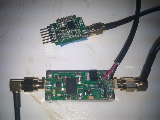
This amplifier gives 12dB transmit gain, and 18dB receive gain, automatically switching between transmit and receive modes when the radio starts and stops transmitting. It can either run on 5V from a UBEC, or can use a builtin switching regulator with a 2S or 3S !LiPo.
We tested this amplifier at one end of a 7.6km link between two hills in Canberra, Australia. At one end we had a simple wire antenna, and at the other end we had a cheap eBay 3.5dBi omni antenna, plus the Shireen amplifier.
This was the test rig at the end without the amplifier
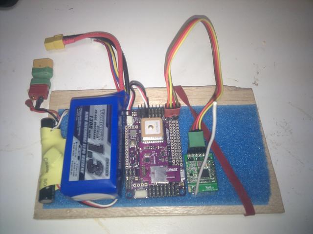
With the following setting:
 S0: FORMAT=22
 S1: SERIAL_SPEED=9
 S2: AIR_SPEED=24
 S3: NETID=25
 S4: TXPOWER=14
 S5: ECC=1
 S6: MAVLINK=1
 S7: OPPRESEND=1
 S8: MIN_FREQ=915000
 S9: MAX_FREQ=928000
 S10: NUM_CHANNELS=50
we found that we got a great link at 7.6 km range. We then progressively lowered the transmit power at each end of the link in order to measure the ‘fade margin’, which allows us to estimate how far the radios could transmit at full power. We found that the fade margin was about 12dB at both ends, which implies that the radios should have been able to sustain a link at approximately 4x the range we tested over.
Note that if you use an amplifier (or high gain antenna) you need to be very careful not to exceed the EIRP level that your local rules allow.
Monitoring the link quality
You can use the MAVLink support in the 3DR Radios to monitor the link quality while flying, if your ground station supports it.
The two key message parameters are RADIO.rssi and RADIO.remrssi. The first is the RSSI (signal strength) level that the local radio is receiving at. The remrssi parameter is the RSSI that the remote radio is receiving at.
Here is a typical graph of the RSSI levels for a flight at my local flying field.
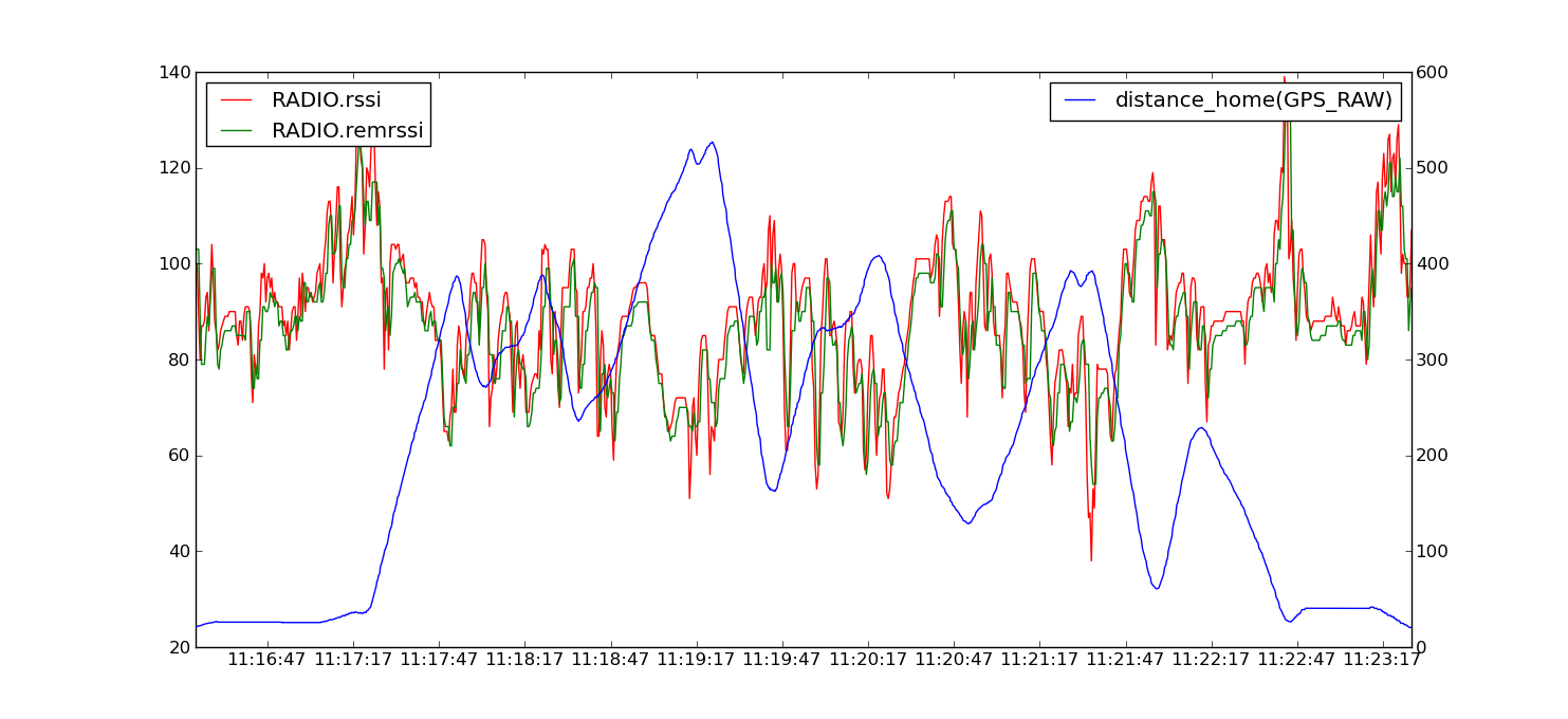
The RSSI value scales approximately as 1.9x the dBm signal strength, plus an offset. See the Si1000 data sheet for the exact mapping between RSSI and dBm received signal strength, or use this approximate formula
signal_dBm = (RSSI / 1.9) - 127
The reason the RSSI varies so much during this flight is that the signal is attenuated when the plane is rolled over in a turn as I was using a simple wire antenna in the plane. The RSSI values for this flight were plenty high enough for the link quality to be excellent throughout the flight using the default radio parameters.
What range can I expect?
The most common question about a telemetry radio is what range you can get with it. It is also a difficult question to answer, as it depends on so many factors.
We have done a lot of test flights to try to gauge what the practical range of these radios is with small omnidirectional antennas and no amplifiers. Here is a typical result:
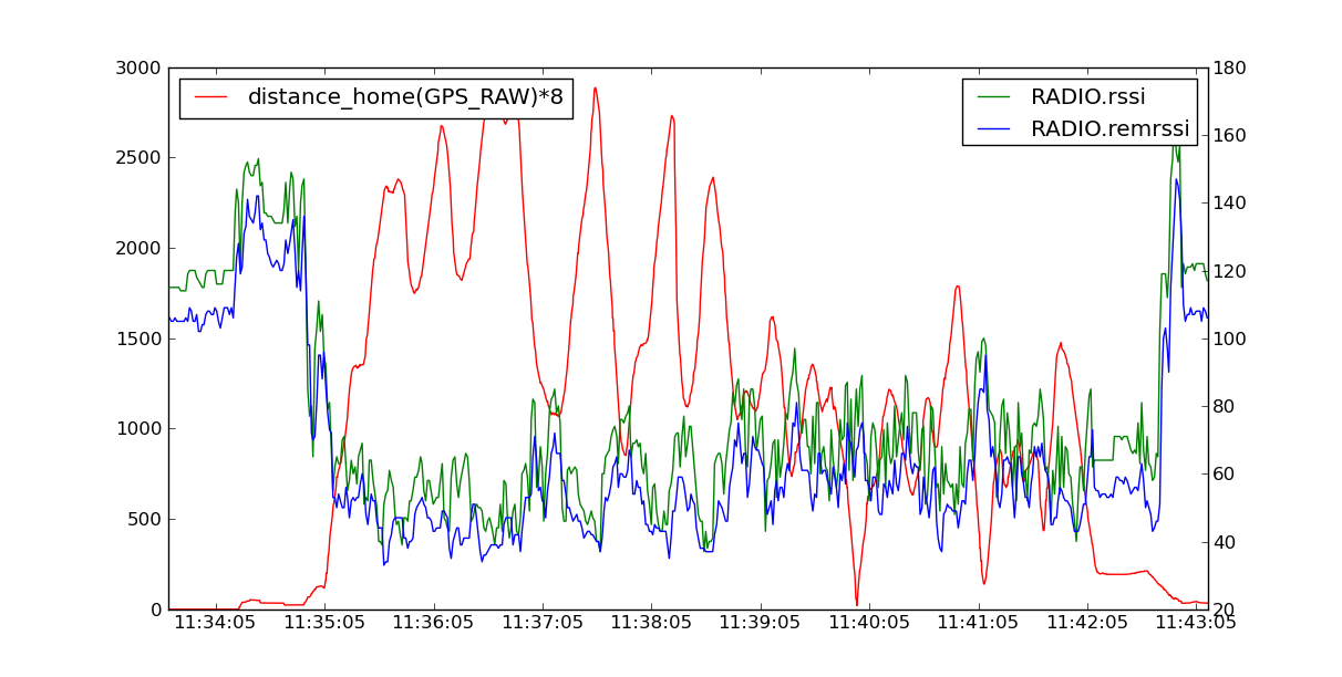
In this case the 3DR 900 radios were setup with default parameters, except that the TXPOWER had been set to 2 dBm, which means they were transmitting with just 1.6% of their maximum power.
Theoretically, a radios range doubles with each additional 6 dB of transmit power, so the range achieved with this test should be about 1/8 of the range that the radios can achieve at an air rate of 64kbps.
That is why the above graph shows the distance in meters times 8. This was on a tiny SkyFun model, and I wanted to keep the plane where I could see it, which is why I did the test with reduced transmit power rather than just flying it a long distance.
The radios kept a perfect link throughout this flight, so we are confident that these radios will achieve a few kilometers range in practice. In this particular case I was flying with a small ‘wire’ antenna in the SkyFun and was using a cheap eBay 3.5dBi antenna on the ground station.
Of course, the range would be considerably better if I had dropped the air data rate. I find 64kbps to be a good rate for general use, but I tend to use 24 kbps if I am wanting to test at longer ranges. The range of these radios has also been confirmed by other users.
For example, I was sent a log showing a good link kept over a flight of 4.5km from the base station, using default radio settings for a 3DR 900 radio. That was using a small omni antenna in the plane, and a 8dB patch antenna on the ground station. The signal level in the log suggests it could have gone quite a bit further.
Diagnosing range problems
If you get less range than you would expect from the above information then what you need to do is graph the noise and signal levels from a flight to work out what the problem is.
The most common source of range problems is noise. Noise is unwanted radio emissions in the same frequency range that your radio is using that interferes with the operation of your radio. The 3DR radios have telemetry logging built in to help you diagnose the source of the noise.
There are three key types of noise that are likely to affect your 3DR radios
noise from the electronics in your aircraft (such as your motor, ESC, APM etc) noise from your ground station computer, especially its USB bus noise from other people operating radios nearby that are on the same frequency as your 3DR radios
To work out what sort of noise you have, open up mission planner and choose the “telemetry logs” tab. Then choose “Tlog>
Kml or Graph”. When the window pops up choose “Graph Log” and select a log from a test flight with your radios. Wait for the log to load, then choose the following items to log:
rssi remrssi noise remnoise
Put all 4 values on the one graph. You will end up with a plot like this:
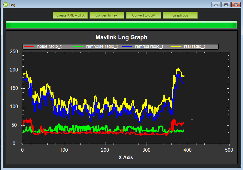
That graph shows you 4 things:
the amount of signal being received on the ground the amount of signal being received in the aircraft the amount of noise being received on the ground the amount of noise being received in the aircraft
For the best possible range you want the two noise lines to be low, and the two signal lines to be high.
In the above graph (taken from my SkyFun with a pair of 3DR-433 radios) you can see that the noise levels in the plane are higher than the noise levels on the ground.
Also note that at the start of the flight (before I started the motor) the noise levels on the plane were lower, then they went up after I started the motor.
That shows I’m getting some noise from my motor. If I wanted more range I would need to move the radio further from the motor and ESC.
Perhaps the most common source of noise with the 3DR-433 is noise from the USB bus on your ground station. That shows up as high values for the RADIO.noise value.
If you get this, then you could try using a different USB cable, or a different laptop. You can also try using a USB hub between your laptop and your radio.
If the ‘rssi’ and ‘noise’ levels meet on the graph then you will lose the link. To determine what your range would be, a rough rule of thumb is to subtract the ‘rssi’ and ‘noise’ numbers, then divide by 2.
That tells you your “fade margin” in decibels. For each 6dB of fade margin your range doubles. So if you have 18dB of fade margin, then you will be able to do roughly 8x whatever range you were at when you measured the margin.
Another key source of range problems is the antenna placement.
Your ground station antenna should be well clear of obstructions and a couple of meters off the ground.
You may need to build a stand to hold it to get the best range.
Upgrading your radio firmware
The firmware for the 3DR radios is open source, and new features are regularly added. You should check for new releases regularly to get the most from your radios.
The easiest way to upgrade is using the APM Mission Planner. Go into the 3DR Radio configuration screen and use the ‘Upload Firmware’ button.
After you upgrade please carefully check all your settings. A firmware update may change your settings to the default values if the EEPROM format has changed.
We also encourage you to get involved in the development of the firmware. Start by looking at the
and contribute some patches!
Forcing bootloader mode
If you somehow manage to get your radio in a state where you can’t upload a new firmware via the Mission Planner then you may need to force the radio into bootloader mode.
The way firmware upload normally works is the planner connects to the radio and sends a AT&UPDATE command to put the radio into bootloader mode ready to receive a new firmware. That only works if the planner can send AT commands to the radio.
If you can’t send AT commands, then you can force bootloader mode by shorting the CTS and GROUND pins on the radio while powering on. The red LED will light up when in bootloader mode.
On the air radios the CTS and GROUND pins are easy to find, as they are marked on the back of the radio (they are two of the FTDI connector pins). On the USB radios it isn’t as obvious, so this diagram may help:

After you have the radio in bootloader mode you should be able to upload a firmware.
3DR Radio Discussion Forum
The best place to get involved with the development or tuning of these radios is the 3DR Radios forum
. Join in on the forum to help make these radios even better!
纠错,疑问,交流: 请进入讨论区或 请点击进入页面,扫码加入微信群或Q群进行交流
获取最新文章: 扫一扫加入“创客智造”公众号